Assertion : Bending a wire does not effect electrical resistance.
Reason : Resistance of wire is proportional ot resistivity of material.
AIIMS 2016, Easy


Download our appand get started for free
Experience the future of education. Simply download our apps or reach out to us for more information. Let's shape the future of learning together!No signup needed.*
Similar Questions
- 1A wire of resistance $x$ ohm is drawn out, so that its length is increased to twice its original length, and its new resistance becomes $20 \,\Omega$, then $x$ will be ........ $\Omega$View Solution
- 2View SolutionWhen cells are connected in parallel, then
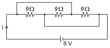
- 3The current $I$ flowing through the given circuit will be $.....A$.View Solution
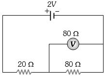
- 4In the adjoining circuit, the $e.m.f.$ of the cell is $2\, volt$ and the internal resistance is negligible. The resistance of the voltmeter is $80 \,ohm$. The reading of the voltmeter will be ............. $volt$View Solution
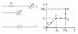
- 5In the circuit shown below (on the left) the resistance and the emf source are both variable. The graph of seven readings of the voltmeter and the ammeter ( $V$ and $I$, respectively) for different settings of resistance and the emf, taken at equal intervals of time $\Delta t$, are shown below (on the right) by the dots connected by the curve $E F G H$. Consider the internal resistance of the battery to be negligible and the voltmeter an ammeter to be ideal devices. (Take, $R_0 \equiv \frac{V_0}{I_0}$ ).View Solution
Then, the plot of the resistance as a function of time corresponding to the curve $E F G H$ is given by
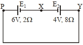
- 6A cell $E _{1}$ of $emf 6 V$ and internal resistance $2 \Omega$ is connected with another cell $E _{2}$ of $emf 4 V$ and internal resistance $8 \Omega$ (as shown in the figure). The potential difference across points $X$ and $Y$ is............ $V$View Solution
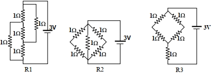
- 7Figure shows three resistor configurations $\mathrm{R} 1, \mathrm{R} 2$ and $\mathrm{R} 3$ connected to $3 \mathrm{~V}$ battery. If the power dissipated by the configuration $\mathrm{R} 1, \mathrm{R} 2$ and $\mathrm{R} 3$ is $\mathrm{P} 1, \mathrm{P} 2$ and $\mathrm{P} 3$, respectively, thenView Solution
Figure:
- 8Consider a metallic cube of edge length $L$. Its resistance, $R$, measured across its opposite faces is $R =\frac{ m _{ e } v }{ ne ^2 L ^2}$, where $n$ is the number density and $v$ is the drift speed of electrons in the cube, and $e$ and $m _{ e }$ are the charge and mass of an electron respectively. Assuming the de-Broglie wavelength of the electron to be $L$, the maximum resistance of the sample is closest to ............. $\,\Omega$ $\left(e=1.60 \times 10^{-19} \,C ; m _{ e }=9.11 \times 10^{-31} \,kg\right.$; Planck's constant, $h=6.63 \times 10^{-34} \,Js$ )View Solution
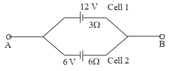
- 9Two cells are connected between points $A$ and $B$ as shown. Cell $1$ has emf of $12\,V$ and internal resistance of $3\,\Omega$. Cell $2$ has emf of $6\,V$ and internal resistance of $6\,\Omega$. An external resistor $R$ of $4\,\Omega$ is connected across $A$ and $B$. The current flowing through $R$ will be $.............A$.View Solution
- 10In an experiment to measure the internal resistance of a cell by potentiometer, it is found that the balance point is at a length of $2\,m$ when the cell is shunted by a $5\,\Omega $ resistance; and is at a length of $3\,m$ when the cell is shunted by a $10\,\Omega $ resistance. The internal resistance of the cell is, then ................ $\Omega $View Solution