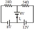
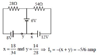
Consider the circuit shown in the figure. The current $I_3$ is equal to
Medium


Download our appand get started for free
Experience the future of education. Simply download our apps or reach out to us for more information. Let's shape the future of learning together!No signup needed.*
Similar Questions
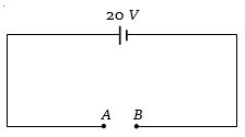
- 1In the shown circuit, what is the potential difference across $A$ and $B$ ......... $V$View Solution
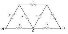
- 2In the circuit shown, the value of each resistance is $r$, then equivalent resistance of circuit between points $A$ and $B$ will beView Solution
- 3A $50\,V$ battery is connected across a $10\, ohm$ resistor. The current is $4.5\, amperes$. The internal resistance of the battery is ............. $ohm$View Solution
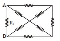
- 4As shown, the circuit is made of $8$ different resistors. It is found that when $R_1 = 4\,\,\Omega,$ the resistance between $A$ and $B$ is $2\,\,\Omega.$ Now replace $R_1$ by a $6\,\,\Omega$ resistor, what is the resistance between $A$ and $B$?View Solution
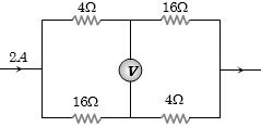
- 5In the circuit shown below, The reading of the voltmeter $V$ is ...........View Solution
- 6View SolutionReferring to the figure below, the effective resistance of the network is
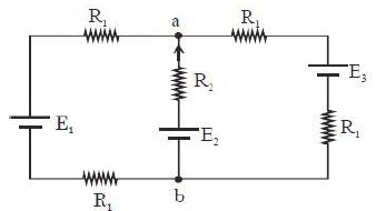
- 7For the circuit shown, with ${R_1} = 1.0\,\Omega $, ${R_2} = 2.0\,\Omega $, ${E_1} = 2\,V$ and ${E_2} = {E_3} = 4\,V$, the potential difference between the points $‘a’$ and $‘b’$ is approximately (in $V$)View Solution
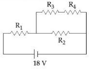
- 8In the given circuit the internal resistance of the $18\,V$ cell is negligible. If $R_1 = 400 \,\Omega ,\,R_3 = 100\,\Omega $ and $R_4 = 500\,\Omega $ and the reading of an ideal voltmeter across $R_4$ is $5\,V,$ then the value of $R_2$ will be ........... $\Omega$View Solution
- 9In the following circuit, $5$ $\Omega$ resistor develops $45$ $J/s$ due to current flowing through it. The power developed per second across $12$ $\Omega$ resistor is ............. $W$View Solution
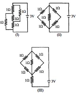
- 10The figure shows three circuits $I, II$ and $III$ which are connected to a $3\,V$ battery. If the powers dissipated by the configurations $I, II$ and $III$ are $P_1 , P_2$ and $P_3$ respectively, thenView Solution