1. Determine the value of phase difference between the current and the voltage in the given series LCR circuit.
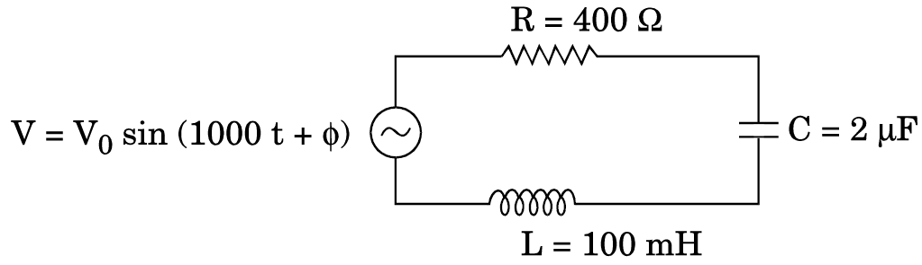
  1. Calculate the value of the additional capacitor which may be joined suitably to the capacitor C that would make the power factor of the circuit unity.
CBSE OUTSIDE DELHI - SET 3 DEHRADUN 2015
Download our app for free and get startedPlay store
  1. In LCR circuit: $\tan\varphi= \frac{\text{X}_{L} - \text{X}_{c}}{\text{R}} = \frac{\text{wL} - \frac{1}{\text{wC}}}{\text{R}}$
Now $\text{X}_{L} = \text{wL} = ( 1000\times100\times10^{-3})\Omega$
$= 100\Omega$
and $\text{X}_{c} = \frac{1}{\text{wc}} = \bigg(\frac{1}{100\times2\times10^{-6}}\bigg)\Omega$
$\therefore\text{X}_{c} = 500 \Omega$
$\therefore\tan\varphi = \frac{500 - 100}{400} = 1 $
$\tan\varphi = 1 $
$\varphi = 45^{o}$
  1. Power Factor:
When power factor = 1, we have $X_L=X_C$
$\therefore\text{X'}_{c} = \frac{1}{\omega\text{C}'} = 100 \Omega$
This gives $\text{C'} = \frac{1}{100\omega} = 10 \mu\text{F}$
We, therefore, need to add a capacitor of capacitance (10-2) μF = 8μF in parallel with the given capacitor.
Alternate Answer
Let addition capacitance $C_1$ be connected:
$\text{X}'_{c} = \frac{1}{1000(2 + \text{C}_{1})\times10^{-6}}$
$\therefore100 = \frac{1}{1000(2 + \text{C}_{1})\times10^{-6}}$
$\therefore2 + \text{C}_{1} = 10 $
$\text{C}_{1} = 8 \mu\text{F}$.
art

Download our app
and get started for free

Experience the future of education. Simply download our apps or reach out to us for more information. Let's shape the future of learning together!No signup needed.*

Similar Questions

  • 1
    Derive an expression for the axial magnetic field of a finite solenoid of length 2l and radius r carrying current I. Under what condition does the field become equivalent to that produced by a bar magnet?
    View Solution
  • 2
    Define the electric resistivity of a conductor.
    Plot a graph showing the variation of resistivity with temperature in the case of a (a) conductor, (b) semiconductor.
    Briefly, explain, how the difference in the behaviour of the two can be explained in terms of number density of charge carriers and relaxation time.
    View Solution
  • 3
    Find the time required for a 50Hz alternating current to change its value from zero to the rms value.
    View Solution
  • 4
    An inductor-coil, a capacitor and an AC source of rms voltage 24V are connected in series. When the frequency of the source is varied, a maximum rms current of 6.0A is observed. If this inductor coil is connected to a battery of emf 12V and internal resistance $4.0\Omega,$ what will be the current?
    View Solution
  • 5
    1. Define the term intensity of radiation' in photon picture.
    2. Plot a graph showing the variation of photo current vs collector potential for three different intensities $I_1 >  I_2 > I_3$, two of which $(I_1$ and $I_2)$ have the same frequency v and the third has frequency $v_1 > v.$
    3. Explain the nature of the curves on the basis of Einstein's equation.
    View Solution
  • 6
    1. Distinguish between a conductor and a semi conductor on the basis of energy band diagram.
    2. The following figure shows the input waveforms (A, B) and the output waveform (Y) of a gate. Identify the gate, write its truth table and draw its logic symbol.
    View Solution
  • 7
    1. Draw a schematic ray diagram of a compound microscope when image is formed at distance of distinct vision.
    2. Write the expression for resolving power of a compound microscope. How can the resolving power of a microscope be increased?
    View Solution
  • 8
    In a series LCR circuit connected to an ac source of variable frequency and voltage v $v_m= \sin, $ draw a plot showing the variation of current (I) with angular frequency ($\omega$) for two different values of resistance R1 and R2(R1 > R2 ). Write the condition under which the phenomenon of resonance occurs. For which value of the resistance out of the two curves, a sharper resonance is produced? Define Q-factor of the circuit and give its significance.
    View Solution
  • 9

    Figure shows a typical circuit for a low-pass filter. An AC input $V_{i }= 10mV$ is applied at the left end and the output $V_0$ is received at the right end. Find the output voltage for ν = 10kHz, 1.0MHz and 10.0MHz. Note that as the frequency is increased the output decreases and, hence, the name low-pass filter.
    View Solution
  • 10
    A voltage $V = V_o$ sin $\omega\text{t}$ is applied to a series LCR circuit. Derive the expression for the average power dissipated over a cycle. Under what condition is (i) no power dissipated even though the current flows through the circuit, (ii) maximum power dissipated in the circuit?
    View Solution