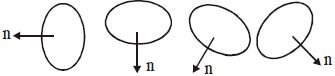
Figure represents four positions of a current carrying coil is a magnetic field directed towards right. $\hat n$ represent the direction of area of vector of the coil. The correct order of potential energy is
Medium


Download our appand get started for free
Experience the future of education. Simply download our apps or reach out to us for more information. Let's shape the future of learning together!No signup needed.*
Similar Questions
- 1Current $I$ is flowing in conductor shaped as shown in the figure. The radius of the curved part is $r$ and the length of straight portion is very large. The value of the magnetic field at the centre $O$ will beView Solution
- 2A charge moving with velocity $v$ in $X$-direction is subjected to a field of magnetic induction in the negative $X$-direction. As a result, the charge willView Solution
- 3Two mutually perpendicular conductors carrying currents $I_1$ and $I_2$ lie in one plane. Locus of the point at which the magnetic induction is zero, is aView Solution
- 4Two concentric coils $X$ and $Y$ of radii $16 \,\,cm$ and $10 \,\,cm$ lie in the same vertical plane containing $N-S$ direction. $X$ has $20$ $turns$ and carries $16 \,\,A.$ $Y$ has $25$ $turns$ $\&$ carries $18\,A$. $X$ has current in anticlockwise direction and $Y$ has current in clockwise direction for an observer, looking at the coils facing the west. The magnitude of net magnetic field at their common centre isView Solution
- 5Two long conductors, separated by a distance $d$ carry current $I_1$ and $I_2$ in the same direction. They exert a force $F$ on each other. Now the current in one of them is increased to two times and its directions is reversed. The distance is also increased to $3d$. The new value of the force between them isView Solution
- 6A galvanometer coil has a resistance of $12\,\Omega $ and meter shows full scale deftection for a current of $3\,mA$ then to convert it into a voltmeter of range $0\,-18\, V$ a resistance should be addedView Solution
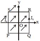
- 7A uniform, constant magnetic field $\vec B$ is directed at an angle of $45^o$ to the $x-$ axis in the $xy-$ plane, $PQRS$ is a rigid square wire frame carrying a steady current $I_0,$ with its centre at the origin $O.$ At time $t = 0,$ the frame is at rest in the position shown in the figure, with its sides parallel to the $x$ and $y$ axis. Each side of the frame is of mass $M$ and Length $L$View Solution
- 8An ammeter gives full deflection when a current of $2\, amp$. flows through it. The resistance of ammeter is $12 \,\Omega$. If the same ammeter is to be used for measuring a maximum current of $5\, amp$., then the ammeter must be connected with a resistance ofView Solution
- 9View SolutionA coil carrying electric current is placed in uniform magnetic field, then
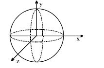
- 10Three rings, each having equal radius $R,$ are placed mutually perpendicular to each other and each having its centre at the origin of co-ordinate system. If current $I$ is flowing thriugh each ring then the magnitude of the magnetic field at the common centre isView Solution