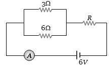
If the ammeter in the given circuit reads $2\, A$, the resistance $R$ is ............ $ohm$
Medium


Download our appand get started for free
Experience the future of education. Simply download our apps or reach out to us for more information. Let's shape the future of learning together!No signup needed.*
Similar Questions
- 1View SolutionWhich is a wrong statement
- 2In the circuit shown in figure, the current drawn from the battery is $4\,A$. If $10 \,\Omega$ resistor is replaced by $20\,\Omega$ resistor, then current drawn from the circuit will be .............. $A$View Solution

- 3A $220\, volt$, $1000\, W$ bulb is connected across a $110\, volt$ mains supply. The power consumed will be ............ $W$View Solution
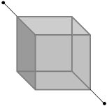
- 4Twelve wires of equal length and same cross-section are connected in the form of a cube. If the resistance of each of the wires is $R$, then the effective resistance between the two diagonal ends would beView Solution
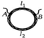
- 5A ring is made of a wire having a resistance $R_0 = 12 \,\,\Omega$. Find the points $A$ and $B,$ as shown in the figure, at which a current carrying conductor should be connected so that the resistance $R$ of the sub circuit between these points is equal to $\frac{8}{3}\,\Omega$.View Solution
- 6In an experiment to measure the internal resistance of a cell by potentiometer, it is found that the balance point is at a length of $2\,m$ when the cell is shunted by a $5\,\Omega $ resistance; and is at a length of $3\,m$ when the cell is shunted by a $10\,\Omega $ resistance. The internal resistance of the cell is, then ................ $\Omega $View Solution
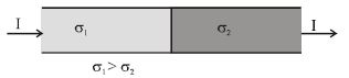
- 7Current $I$ is flowing through the two materials having electrical conductivities $\sigma_1$ and $\sigma_2$ respectively $(\sigma_1 > \sigma_2 )$ as shown in the figure. The total amount of charge at the junction of the materials isView Solution
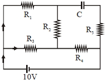
- 8An ideal cell of emf $10\, V$ is connected in circuit shown in figure. Each resistance is $2\, \Omega .$ The potential difference (in $V$) across the capacitor when it is fully charged isView Solution
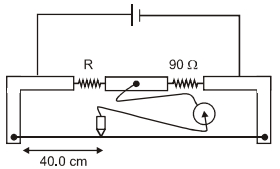
- 9During an experiment with a metre bridge, the galvanometer shows a null point when the joceky is pressed at $40.0 \ cm$ using a standard resistance of $90 \ \Omega$, as shown in the figure. The least count of the scale used in the meter bridge is $1 \ mm$. The unknown resistance is:View Solution
- 10Three resistances $P, Q, R$ each of $2 \,\,\Omega$ and an unknown resistance $S$ form the four arms of a Wheatstone bridge circuit. When a resistance of $6 \,\,\Omega$ is connected in parallel to $S$ the bridge gets balanced. What is the value of $S\,?$ ............... $\Omega$View Solution