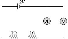
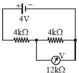
In the circuit shown, $A$ and $V$ are ideal ammeter and voltmeter respectively. Reading of the voltmeter will be ............... $V$
Easy
Download our app for free and get started
(d) Zero (No potential difference across voltmeter).

Download our appand get started for free
Experience the future of education. Simply download our apps or reach out to us for more information. Let's shape the future of learning together!No signup needed.*
Similar Questions
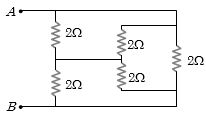
- 1Find the equivalent resistance across $AB$ .............. $\Omega$View Solution
- 2Copper and silicon is cooled from $300\; K$ to $60\; K$, the specific resistanceView Solution
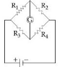
- 3The Wheatstone bridge shown in Fig. here, gets balanced when the carbon resistor used as $R_1$ has the colour code (Orange, Red, Brown). The resistors $R_2$ and $R_4$ are $80\, \Omega $ and $40\,\Omega $, respectively. Assuming that the colour code for the carbon resistors gives their accurate values, the colour code for the carbon resistor, used as $R_3$ would beView Solution
- 4Three resistors each of $4\,\Omega $ are connected together to form a network. The equivalent resistance of the network cannot be ............ $\Omega$View Solution
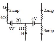
- 5In the part of a circuit shown in the figure, the potential difference $(V_G -V_H)$ between points $G$ and $H$ will be ............... $V$View Solution
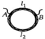
- 6A ring is made of a wire having a resistance $R_0 = 12 \,\,\Omega$. Find the points $A$ and $B,$ as shown in the figure, at which a current carrying conductor should be connected so that the resistance $R$ of the sub circuit between these points is equal to $\frac{8}{3}\,\Omega$.View Solution
- 7The percentage error in the reading of the voltmeter in the figure shown here is nearly ............ $\%$View Solution
- 8View SolutionThe example for non-ohmic resistance is
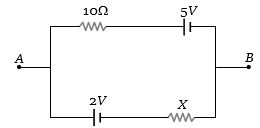
- 9If ${V_{AB}} = 4\,V$ in the given figure, then resistance $X$ will be .............. $\Omega$View Solution
- 10The e.m.f. of a cell is $E\, volts$ and internal resistance is $r$ $ohm$. The resistance in external circuit is also $r$ $ohm$. The p.d. across the cell will beView Solution