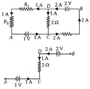
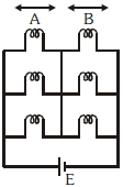
In the circuit shown in the figure, if the potential at point $A$ is taken to be zero, the potential at point $B$ is ................ $V$
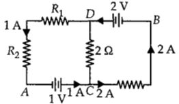
AIPMT 2011, Medium


Download our appand get started for free
Experience the future of education. Simply download our apps or reach out to us for more information. Let's shape the future of learning together!No signup needed.*
Similar Questions
- 1A storage cell is charged by $5\, amp$ $D.C.$ for $18$ hours. Its strength after charging will be .............. $AH$View Solution
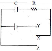
- 2The capacitor $C$ is initially without charge.$X$ is now j oined to $Y$ for a long time, during which $H_1$ heat is produced in the resistance $R$. $X-Y$ connection is removed and $X$ is now joined to $Z$ for a long time, during which heat $H_2$ is produced in $R$.View Solution
- 3The potential difference in open circuit for a cell is $2.2\, volts$. When a $4\, ohm$ resistor is connected between its two electrodes the potential difference becomes $2\, volts$. The internal resistance of the cell will be .............. $ohm$View Solution
- 4Six similar bulbs are connected as shown in the figure with a $DC$ source of $emf\; E$, and zero internal resistance. The ratio of power consumption by the bulbs when $(i)$ all are glowing and $(ii)$ in the situation when two from section $A$ and one from section $B$ are glowing, will beView Solution
- 5View SolutionThe arrangement as shown in figure is called as
- 6What amount of heat will be generated in a coil of resistance $R$ due to a charge $q$ passing through it if the current in the coil decreases to zero uniformly during a time interval $\Delta t$View Solution
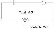
- 7A battery of $e.m.f.$ $10\, V$ and internal resistance $0.5\, ohm$ is connected across a variable resistance $R$. The value of $R$ for which the power delivered in it is maximum is given by ......... $ohm$View Solution
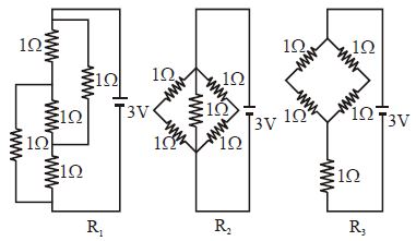
- 8Figure shows three resistor configurations $R_1,R_2$ and $R_3$ connected to $3\,V$ battery. If the power dissipated by the configuration $R_1, R_2$ and $R_3$ is $P_1, P_2$ and $P_3$ , respectively thenView Solution
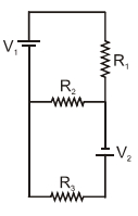
- 9Two ideal batteries of emf $V _1$ and $V _2$ and three resistances $R _1, R _2$ and $R _3$ are connected as shown in the figure.View Solution
The current in resistance $R _2$ would be zero if
$(A)$ $V_1=V_2$ and $R_1=R_2=R_3$
$(B)$ $V_1=V_2$ and $R_1=2 R_2=R_3$
$(C)$ $V_1=2 V_2$ and $2 R_1=2 R_2=R_3$
$(D)$ $2 V _1= V _2$ and $2 R _1= R _2= R _3$
- 10In the circuit shown, the reading of the Ammeter is doubled after the switch is closed. Each resistor has a resistance $1\,\Omega$ and the ideal cell has an $e.m.f.$ $10\,V$. Then, the Ammeter has a coil resistance equal to ............ $\Omega$View Solution