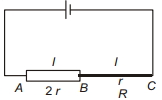
In the following diagram, the lengths of wires $A B$ and $B C$ are equal, but the radius of wire $A B$ is double that of $B C$. The ratio of potential gradient on wires $A B$ and on $B C$ will be (wires are made of same material)
Medium


Download our appand get started for free
Experience the future of education. Simply download our apps or reach out to us for more information. Let's shape the future of learning together!No signup needed.*
Similar Questions
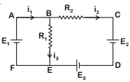
- 1For the circuit given below, the Kirchoff's loop rule for the loop $BCDEB$ is given by the equationView Solution
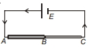
- 2View SolutionIn the circuit shown in the figure, the current through
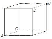
- 3A cube is formed with ten identical resistances $R$ (thick lines) and two shorting wires (dotted lines) along the arms $A C$ and $B D$ as shown in the figure below. Resistance between point $A$ and $B$ is ...........$\Omega$View Solution
- 4Two electric bulbs have tungsten filament of same length. If one of them gives $60\ W$ and the other $100\ W$ , thenView Solution
- 5The voltage of clouds is $4 \times 10^6\,volt$ with respect to round. In a lighteing strike lasting $100\,m\,sec$, a charge of $4\,coulombs$ is delivered to the ground. The power of lightening strike isView Solution
- 6The potential difference in open circuit for a cell is $2.2\, volts$. When a $4\, ohm$ resistor is connected between its two electrodes the potential difference becomes $2\, volts$. The internal resistance of the cell will be .............. $ohm$View Solution
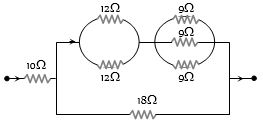
- 7In the following circuit, $18\,\Omega $ resistor develops $2\,J/sec$ due to current flowing through it. The power developed across $10\,\Omega $ resistance is .............. $W$View Solution
- 8The current flowing through $R _2$ is:View Solution
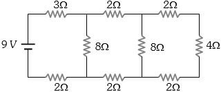
- 9View SolutionDiagram shows a circuit diagram choose incorrect statement
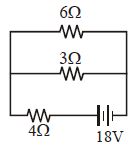
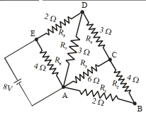
- 10The total power dissipated (in $watt$ ) in the circuit shown isView Solution