Question
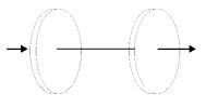
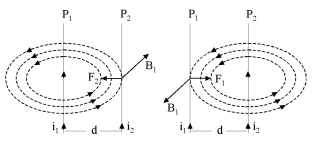
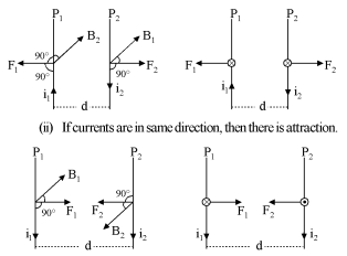
Obtain expression for force on unit length of two straight parallel current carrying conductors. Under what conditions is this force attractive or repulsive? Define the standard unit of electric current.

Answer

Force between Two Parallel Current Carrying Conductors :
In the given figure, $P _1$ and $P _2$ are two current carrying conductors of infinite length which are situated at a distance $d$ from each other in the plane of the paper.
Current $i_1$ and $i_2$ are flowing in the same direction in the two wires and due to this magnetic field will be produced around them.
Here one current carrying conductor is present in the produced magnetic field due to other current carrying conductor.
Magnetic field produced at a distance $d$ due to current carrying conductor $P _1$
$ B_1=\frac{\mu_0 i_1}{2 \pi d} $
Force acting on length $/$ of current carrying conductor $P _2$ present in this magnetic field
$\overrightarrow{ F }_2={ }_{i_2}\left(\vec{l} \times \overrightarrow{ B }_1\right)$
$F _2=i_2 / B _1 \sin \theta$
$F _2=i_2 / B _1$
$\because\left[\vec{l} \perp \overrightarrow{B}_1\right] $
On putting value of $B _1$ from equation $(1)$,
$ F_2=i_2 l \times \frac{\mu_{o} i_1}{2 \pi d}$
$F_2=\frac{\mu_{o} i_2 l}{2 \pi d}$ Newton 
Direction of this force $F _2$ is perpendicular to the current carrying conductor $P _2$ and magnetic force $B _1$ produced on it.
Hence this force is inward the plane of paper and towards conductor $P _1$.
This direction of force can be determined with the help of Fleming's left$-$hand rule.
$ \frac{F_2}{T}=\frac{\mu_0 i_1 i_2}{2 \pi d} N / m $
This is magnetic force working on unit length of current carrying conductor $P _2$.
Magnetic field produced at a distance $d$ due to current carrying conductor
$P _2$. $ B_2=\frac{\mu_0 i_2}{2 \pi d} $
Magnetic field working on unit length $/$ of $P _1$ due to $P _2$,
$\overrightarrow{ F }_1=i_1\left(\vec{l} \times \overrightarrow{ B }_2\right)$ or $ F _1=i_1 / B _2$
or $F _1=\frac{i_1 / \mu_0 i_2}{2 \pi d}$
Image
or $ F _1=\frac{\mu_0 i_1 i_2 l}{2 \pi d}$
or $ \frac{F_1}{T}=\frac{\mu_0 i_1 i_2}{2 \pi d}\  N / m $
From equations $(3)$ and $(4),$
$ \frac{F_1}{T}=\frac{F_2}{l}=\frac{\mu_{o} i_1 i_2}{2 \pi d}\ N / m $
It is clear from the figure that when current in two parallel current carrying conductors is in the same direction, force of attraction is exerted between them.
Special conditions :
$(i)$ If currents are in mutually opposite directions, then there will be repulsion
Image
Mutual force acting on each wire per unit length of two parallel wires
$\frac{ F _1}{l}=\frac{\mu_0}{2 \pi}\left(\frac{i_1 i_2}{d}\right) N / m$
But $\mu_0=4 \pi \times 10^{-7} N / m ^2$
Hence, $\frac{ F _1}{l}=\frac{4 \pi \times 10^{-7}}{2 \pi}\left(\frac{i_1 i_2}{d}\right)\ N / m$
$=\left(2 \times 10^{-7}\right)\left(\frac{i_1 i_2}{d}\right) N / m$
If $i_1=i_2=i$ ampere and $d=1 m$, then $F _{1 / l}=\left(2 \times 10^{-7}\right) i^2\ N / m$
Therefore, if the force applied per meter length between these wires is $2 \times 10^{-7}$ then $1$ Ampere current will flow through the wires.
So $1$ ampere is that electric current which when flows through two straight, long and parallel wires kept at a distance of $1 m$ from each other in air $($or vacuum$)$ exerts a force of $2 \times 10^{-7}\ N / m$ on one meter length of each wire.

Need a full question paper?

Generate a complete, print-ready paper with questions like this in minutes — across 16+ boards, with answer keys.

Start Generating Free

Similar questions

Find the mass M of the hanging block in figure which will prevent the smaller block from slipping over the triangular block. All the surfaces are frictionless and the strings and the pulleys are light.
The image of a small electric bulb fixed on the wall of a room is to be obtained on the opposite wall 3 m away by means of a large convex lens. What is the maximum possible focal length of the lens required for the purpose?
Three coplanar parallel wires, each carrying a current of 10A along the same direction, are placed with a separation 5.0cm between the consecutive ones. Find the matnitude ol the magnetic force per unit lenght acting on the wires.
Two vessels $A$ and $B$ of equal volume $V_0$ are connected by a narrow tube that can be closed by a valve. The vessels are fitted with pistons that can be moved to change the volumes. Initially, the valve is open and the vessels contain an ideal gas $\Big(\frac{\text{C}_\text{P}}{\text{C}_\text{V}}=\gamma\Big)$ at atmospheric pressure $p_0$ and atmospheric temperature $T_0.$ The walls of vessel $A$ are diathermic and those of $B$ are adiabatic. The valve is now closed and the pistons are slowly pulled out to increase the volumes of the vessels to double the original value.
  1. Find the temperatures and pressures in the two vessels.
  2. The valve is now opened for sufficient time so that the gases acquire a common temperature and pressure. Find the new values of the temperature and pressure.
The given figure shows a capacitor made of two circular plates each of radius 12 cm, and separated by 5.0 cm. The capacitor is being charged by an external source (not shown in the figure). The charging current is constant and equal to 0.15 A.
(a) Calculate the capacitance and the rate of change of potential difference between the plates.
(b) Obtain the displacement current across the plates.
(c) Is Kirchhoff's first rule (junction rule) valid at each plate of the capacitor? Explain.
Image
Two steel rods and an aluminium rod of equal length $l_0$ and equal cross section are joined rigidly at their ends as shown in the figure below. All the rods are in a state of zero tension at $0^\circ C$. Find the length of the system when the temperature is raised to $\theta$. Coefficient of linear expanaion of aluminium and steel are $\alpha_\text{a}$ and $\alpha_\text{s}$respectively. Young's modulus of aluminium is $Y_a$ and of steel is $Y_s.$
Draw a ray diagram to show the formation of real image of the same size as that of the object placed in front of a converging lens. Using this ray diagram establish the relation between u, v and f for this lens.
Explain Hertz experiment for communication of electromagnetic waves. Draw labelled diagram of apparatus used in the experiment.
$(or)$
Explain Hertz experiment related with electromagnetic waves and also explain experiments of Jagdish Chandra Basu and Marconi.
$(or)$
Critically evaluate Hertz experiment of production and communication of electromagnetic waves.
Figure shows a transparent hemisphere of radius 3.0cm made of a material of refractive index 2.0.
  1. A narrow beam of parallel rays is incident on the hemisphere as shown in the figure. Are the rays totally reflected at the plane surface?
  2. Find the image formed by the refraction at the first surface.
  3. Find the image formed by the reflection or by the refraction at the plane surface.
  4. Trace qualitatively the final rays as they come out of the hemisphere.
Two convex lenses, each of focal length $10\ cm,$ are placed at a separation of $15\ cm$ with their principal axes coinciding,
  1. Show that a light beam coming parallel to the principal axis diverges as it comes out of the lens system.
  2. Find the location of the virtual image formed by the lens system of an object placed far away.
  3. Find the focal length of the equivalent lens.
$($Note that the sign of the focal length is positive although the lens system actually diverges a parallel beam incident on it$)$.