Question
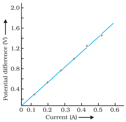
State Ohm’s law? How can it be verified experimentally? Does it hold good under all conditions? Comment.
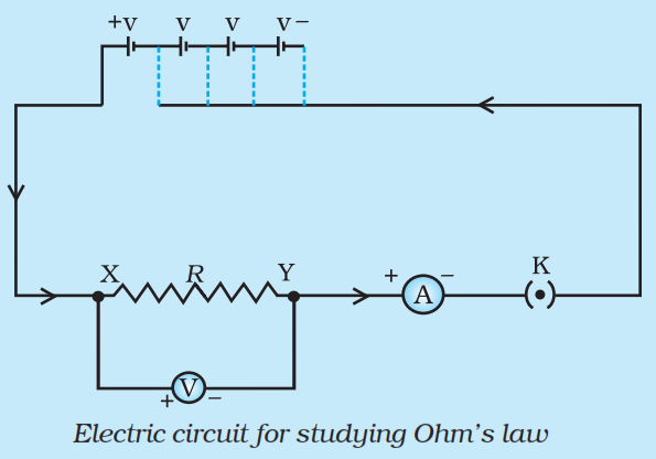
Answer

According to Ohm's law the electric current flowing through a conductor is directly proportional to the potential difference applied across its ends provided the physical conditions such as temperature etc remains unchanged.LetVbe the potential difference applied across the ends of conductor through which currentIflows, then according to Ohm's law.$\text{V}\propto\text{I}\Rightarrow\ \text{V}=\text{IR}$Ohm’s law can be verified experimentally by the activity given below:
  1. Firstly, Set up a circuit as shown in figure given below, consisting of a nichrome wire XY of length, say 0.5m, an ammeter, a voltmeter and four cells of 1.5V each. (Nichrome is an alloy of nickel,chromium, manganese, and iron metals.)

  1. First use only one cell as the source in the circuit. Note the reading in the ammeterI,for the current and reading of the voltmeterVfor the potential difference across the nichrome wire XY in the circuit. Tabulate them in the Table given.
  2. Next connect two cells in the circuit and note the respective readings of the ammeter and voltmeter for the values of current through the nichrome wire and potential difference across the nichrome wire.
  3. Repeat the above steps using three cells and then four cells in the circuit separately.
  4. Calculate the ratio of V to I for each pair of potential difference V and current I.
S.No.Number of cells used in the circuitCurrent through the nichrome wire, I (ampere)Potential difference across the nichrome wire, V (Volt)$\frac{\text{V}}{\text{I}}$$\Big(\frac{\text{Volt}}{\text{Ampere}}\Big)$
1.1
2.2
3.3
4.4
  1. Plot a graph between V and I. The graph will be a straight line as shown below.

  1. This verifies the Ohm’s law.
Ohm's does not hold under all conditions as it is basically not a fundamental law which means it has exceptions. Following are the conditions when Ohm’s law does not hold:
  • It is not obeyed when physical conditions of conductors like temperature keep on changing.
  • It is not obeyed by a lamp filament, junction diode, thermistor etc.
  • It is not obeyed in case of superconductors whose resistance is equal to zero.

Need a full question paper?

Generate a complete, print-ready paper with questions like this in minutes — across 16+ boards, with answer keys.

Start Generating Free

Similar questions

If a concave mirror has a focal length of 10cm, find the two positions where an object can be placed to give, in each case, an image twice the height of the object.
For the circuit shown in the diagram given below:

Calculate:
  1. The value of current through each resistor.
  2. The total current in the circuit.
  3. The total effective resistance of the circuit.
The diagram shows a dish antenna which is used to receive television signals from a satellite. The antenna (signal detector) is fixed in front of the curved dish.

  1. What is the purpose of the dish?
  2. Should it be concave or convex?
  3. Where should the antenna be positioned to receive the strongest possible signals?
  4. Explain what change you would expect in the signals if a larger dish was used.
Two resistors, with resistances $ 5 Ω$ and $10 Ω$ respectively are to be connected to a battery of emf 6V so as to obtain:
  1. Minimum current flowing.
  2. Maximum current flowing.
  1. How will you connect the resistances in each case?
  2. Calculate the strength of the total current in the circuit in the two cases.
  1. Define the following terms in the context of spherical mirrors:
  1. Pole.
  2. Centre of curvature.
  3. Radius of curvature.
  4. Principal axis.
  1. Draw ray diagrams to show the principal focus of (i) a concave mirror, and (ii) a convex mirror.
  2. In the following diagram, MM' is a concave mirror and AB is an object. Draw on your answer-sheet a ray diagram to show the formation of image of this object.

State whether an electric heater will consume more electrical energy or less electrical energy per second when the length of its heating element is reduced. Give reasons for your answer.
State and explain the laws of reflection of light at a plane surface (like a plane mirror), with the help of a labelled ray-diagram. Mark the angles of ‘incidence’ and ‘reflection’ clearly on the diagram. If the angle of reflection is 47.5°, what will be the angle of incidence?
Why does a light ray incident on a rectangular glass slab immersed in any medium emerges parallel to itself? Explain using a diagram.
  1. One-half of a convex lens is covered with a black paper. Will such a lens produce an image of the complete object? Support your answer with a ray diagram.
  2. An object 5 cm high is held 25 cm away from a converging lens of focal length 10 cm.
  1. Draw the ray diagram.
  2. Calculate the position and size of the image formed.
  3. What is the nature of the image?
An object 3cm high is placed at a distance of 8cm from a concave mirror which produces a virtual image 4.5cm high:
  1. What is the focal length of the mirror?
  2. What is the position of image?
  3. Draw a ray-diagram to show the formation of image.