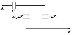
The equivalent capacitance between $A$ and $B$ in the figure is $1\,\mu F$. Then the value of capacitance $C$ is.....$\mu F$
Medium


Download our appand get started for free
Experience the future of education. Simply download our apps or reach out to us for more information. Let's shape the future of learning together!No signup needed.*
Similar Questions
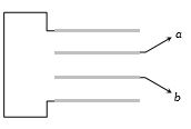
- 1Four metallic plates each with a surface area of one side $A$ are placed at a distance $d$ from each other. The plates are connected as shown in the circuit diagram. Then the capacitance of the system between $a$ and $b$ isView Solution
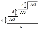
- 2A capacitor is made of a tlat plate of area $A$ and a second plate having a stair-like structure as shown in figure. If the area of each stair is $\frac{A}{3}$ and the height is $\mathrm{d}$, the capacitance of the arrangement is:View Solution
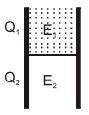
- 3A parallel plate capacitor has a dielectric slab of dielectric constant $K$ between its plates that covers $1 / 3$ of the area of its plates, as shown in the figure. The total capacitance of the capacitor is $C$ while that of the portion with dielectric in between is $C _1$. When the capacitor is charged, the plate area covered by the dielectric gets charge $Q_1$ and the rest of the area gets charge $Q_2$. Choose the correct option/options, igonoring edge effects.View Solution
$(A)$ $\frac{E_1}{E_2}=1$ $(B)$ $\frac{E_1}{E_2}=\frac{1}{K}$ $(C)$ $\frac{Q_1}{Q_2}=\frac{3}{K}$ $(D)$ $\frac{ C }{ C _1}=\frac{2+ K }{ K }$
- 4A $5\, \mu F$ capacitor is charged fully by a $220\,V$ supply. It is then disconnected from the supply and is connected in series to another uncharged $2.5\;\mu F$ capacitor. If the energy change during the charge redistribution is $\frac{ X }{100} \;J$ then value of $X$ to the nearest integer is$.....$View Solution
- 5Two unlike charges of magnitude $q$ are separated by a distance $2d$. The potential at a point midway between them isView Solution
- 6Two parallel plate capacitors $C_1$ and $C_2$ each having capacitance of $10 \mu F$ are individually charged by a $100\,V$ $D.C.$ source. Capacitor $C _1$ is kept connected to the source and a dielectric slab is inserted between it plates. Capacitor $C _2$ is disconnected from the source and then a dielectric slab is inserted in it. Afterwards the capacitor $C_1$ is also disconnected from the source and the two capacitors are finally connected in parallel combination. The common potential of the combination will be $.........V.$ (Assuming Dielectric constant $=10$ )View Solution
- 7Kinetic energy of an electron accelerated in a potential difference of $100\, V$ isView Solution
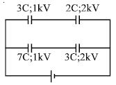
- 8The diagram shows four capacitors with capacitances and break down voltages as mentioned. What should be the maximum value of the external emf source such that no capacitor breaks down ? .......$kV$View Solution
- 9A parallel plate capacitor filled with a medium of dielectric constant $10$ , is connected across a battery and is charged. The dielectric slab is replaced by another slab of dielectric constant $15$ . Then the energy of capacitor will ......................View Solution
- 10Two identical capacitors are joined in parallel, charged to potential $V$, separated and then, connected in series, $i.e.$, the positive plate of one is connected to the negative plate of the other. ThenView Solution