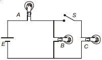
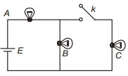
Three identical bulbs are connected as shown in figure. When switch $S$ is closed, the power consumed in bulb $B$ is $P$. What will be the power consumed by the same bulb when switch $S$ is opened?
Medium


Download our appand get started for free
Experience the future of education. Simply download our apps or reach out to us for more information. Let's shape the future of learning together!No signup needed.*
Similar Questions
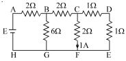
- 1The figure shows a network of resistors and $a$ battery. If $1\,A$ current flowsthrough the branch $CF$, then answer the following questions The $\mathrm{emf}$ $E$ of the battery is If a zero resistance wire is connected in parallel to branch $CF$ ............... $V$View Solution
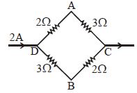
- 2A current of $2\, A$ flows in a system of conductors as shown. The potential difference $(V_A -V_B)$ will be ................ $\mathrm{V}$View Solution
- 3The thermo $e.m.f.$ of a thermo-couple is $25\,\mu V{/^o}C$ at room temperature. A galvanometer of $40\, ohm$ resistance, capable of detecting current as low as ${10^{ - 5}}\,A,$ is connected with the thermocouple. The smallest temperature difference that can be detected by this system is ................ $^oC$View Solution
- 4A uniform heating wire of resistance $36\, \Omega$ is connected across a potential difference of $240\, {V}$ The wire is then cut into half and potential difference of $240\, {V}$ is applied across each half separately. The ratio of power dissipation in first case to the total power dissipation in the second case would be $1: {x}$, where ${x}$ is........... .View Solution
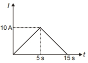
- 5Current $l$ versus time $t$ graph through a conductor is shown in the figure. Average current through the conductor in the interval $0$ to $15 \,s$ is ............ $A$View Solution
- 6View SolutionAssertion : Bending a wire does not effect electrical resistance.
Reason : Resistance of wire is proportional ot resistivity of material.
- 7A Copper $(Cu)$ rod of length $25\, {cm}$ and cross- sectional area $3\, {mm}^{2}$ is joined with a similar Aluminium $(Al)$ rod as shown in figure. Find the resistance of the combination between the ends $A$ and $B$ (in ${m} \Omega$)View Solution
(Take Resistivity of Copper $=1.7 \times 10^{-8}\, \Omega \,{m}$, Resistivity of Aluminium $=2.6 \times 10^{-8}\, \Omega \,{m}$ )

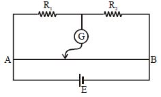
- 8In the fig. shown for given values of $R_1$ and $R_2$ the balance point for jockey is at $40\, cm$ from $A$. When $R_2$ is shunted by a resistance of $10\,\Omega $, balance shifts to $50\, cm. R_1$ and $R_2$ are $(AB = 1\,m)$View Solution
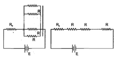
- 9In the circuit shown, $n$-identical resistors $R$ are connected in parallel $(n > 1)$ and the combination is connected in series to another resistor $R_0$. In the adjoining circuit $n$ resistors of resistance $R$ are all connected in series alongwith $R_0$. The batteries in both circuits are identical and net power dissipated in the $n$ resistors in both circuits is same. The ratio $R_0 / R$ isView Solution
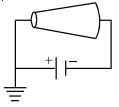
- 10$A$ conductor is made of an isotropic material and has shape of a truncated cone. $A$ battery of constant emf is connected across it and its left end is earthed as shown in figure. If at a section distant $x$ from left end, electric field intensity, potential and the rate of generation of heat per unit length are $E, V$ and $H$ respectively, which of the following graphs is are correct?View Solution