Question
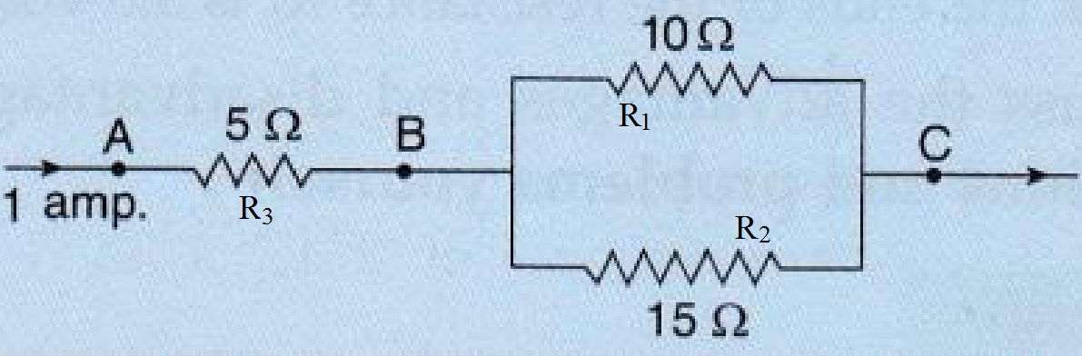
Three resistors are connected as shown in the diagram.
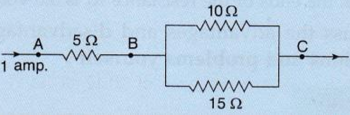
Through the resistor 5 ohm, a current of 1 ampere is flowing,
Through the resistor 5 ohm, a current of 1 ampere is flowing,
- What is the current through the other two resistors?
- What is the p.d. across AB and across AC?
- What is the total resistance?