Two bulbs are in parallel and they together consume $48\, W$ from a battery of $6\, V$. The resistance of each bulb is ............ $\Omega$
Easy


Download our appand get started for free
Experience the future of education. Simply download our apps or reach out to us for more information. Let's shape the future of learning together!No signup needed.*
Similar Questions
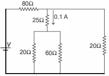
- 1A current of $0.1 \,A$ flows through a $25 \,\Omega$ resistor represented by the circuit diagram. The current in $80 \,\Omega$ resistor is ........... $A$View Solution
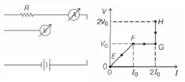
- 2In the circuit shown below (on the left) the resistance and the emf source are both variable. The graph of seven readings of the voltmeter and the ammeter ( $V$ and $I$, respectively) for different settings of resistance and the emf, taken at equal intervals of time $\Delta t$, are shown below (on the right) by the dots connected by the curve $E F G H$. Consider the internal resistance of the battery to be negligible and the voltmeter an ammeter to be ideal devices. (Take, $R_0 \equiv \frac{V_0}{I_0}$ ).View Solution
Then, the plot of the resistance as a function of time corresponding to the curve $E F G H$ is given by
- 3An aluminium wire is stretched to make its length, $0.4 \,\%$ larger. Then percentage change in resistance is $.....\,\%$View Solution
- 4A filament bulb $(500 \,W,\,\, 100 \,V)$ is to be used in a $230\, V$ main supply. When a resistance $R$ is connected in series, it works perfectly and the bulb consumes $500\,W.$ The value of $R$ is .................. $\Omega$View Solution
- 5In the adjoining circuit, the potential difference across $3\,\,\Omega $ is ................ $\mathrm{V}$View Solution
- 6$A$ battery consists of a variable number $n$ of identical cells having internal resistance connected in series. The terminals of the battery are short circuited and the current $I$ measured. Which one of the graph below shows the relationship between $I$ and $n$?View Solution
- 7The current in a conductor is expressed as $I=3 t^2+4 t^3$, where $I$ is in Ampere and $t$ is in second. The amount of electric charge that flows through a section of the conductor during $t=1$ s to $t=2 \mathrm{~s}$ is_______ C.View Solution
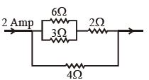
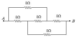
- 8Effective resistance between $A$ and $B$ is ........... $\Omega$View Solution
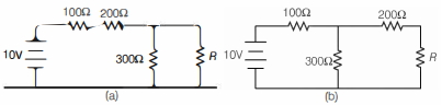
- 9A student was trying to construct the circuit shown in the figure below marked $(a)$, but ended up constructing the circuit marked $(b)$. Realising her mistake, she corrected the circuit, but to her surprise, the output voltage (across $R$ ) did not change. The value of resistance $R$ is ............ $\Omega$View Solution
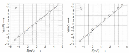
- 10Two students $P$ and $Q$ perform an experiment to verify Ohm's law for a conductor with resistance $R$. They use a current source and a voltmeter with least counts of $0.1 mA$ and $0.1 \,mV$, respectively. The plots of the variation of voltage drop $V$ across $R$ with current $I$ for both are shown below. The statement which is most likely to be correct?View Solution