Two resistance wires on joining in parallel the resultant resistance is $\frac{6}{5}\,ohms$. One of the wire breaks, the effective resistance is $2\,ohms$. The resistance of the broken wire is ............ $ohm$
Medium


Download our appand get started for free
Experience the future of education. Simply download our apps or reach out to us for more information. Let's shape the future of learning together!No signup needed.*
Similar Questions
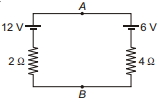
- 1Potential difference across $A B$ i.e., $V_A-V_B$ is ......... $V$View Solution
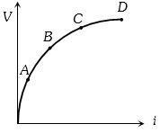
- 2Variation of current passing through a conductor as the voltage applied across its ends as varied is shown in the adjoining diagram. If the resistance $(R)$ is determined at the points $A$, $B$, $C$ and $D$, we will find thatView Solution
- 3View SolutionThe potentiometer is best for measuring voltage, as
- 4View SolutionIn the circuit shown in the figure below, which of the following statement is incorrect ?
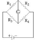
- 5The Wheatstone bridge shown in Fig. here, gets balanced when the carbon resistor used as $R_1$ has the colour code (Orange, Red, Brown). The resistors $R_2$ and $R_4$ are $80\, \Omega $ and $40\,\Omega $, respectively. Assuming that the colour code for the carbon resistors gives their accurate values, the colour code for the carbon resistor, used as $R_3$ would beView Solution
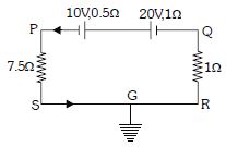
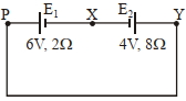
- 6A cell $E _{1}$ of $emf 6 V$ and internal resistance $2 \Omega$ is connected with another cell $E _{2}$ of $emf 4 V$ and internal resistance $8 \Omega$ (as shown in the figure). The potential difference across points $X$ and $Y$ is............ $V$View Solution
- 7A heating element has a resistance of $100\,\Omega $ at room temperature. When it is connected to a supply of $220\,V,$ a steady current of $2\,A$ passes in it and temperature is $500\,^oC$ more than room temperature. What is the temperature coefficient resistance of the heating element?View Solution
- 8The balancing length for a cell is $560 \;\mathrm{cm}$ in a potentiometer experiment. When an external resistance of $10 \;\Omega$ is connected in parallel to the cell, the balancing length changes by $60\; \mathrm{cm} .$ If the internal resistance of the cell is $\frac{\mathrm{N}}{10} \;\Omega,$ where $\mathrm{N}$ is an integer then value of $\mathrm{N}$ isView Solution
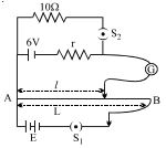
- 9In the arrangement shown in figure when the switch $S_2$ is open, the galvanometer shows no deflection for $l = L/2$. When the switch $S_2$ is closed, the galvanometer shows no deflection for $l = 5L /12$ . The internal resistance $(r)$ of $6\, V$ cell, and the $\mathrm{emf}$ $E$ of the other battery are respectivelyView Solution
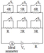
- 10Say switches $S_1, S_2$ and so on upto $S_6$ are closed, one after other in order (first $S_1$, then $S_2$) at regular intervals of $1$ minute starting from $t = 0$. The graph of current versus time is best represented asView Solution