With a potentiometer null point were obtained at $140\, cm$ and $180\, cm$ with cells of $emf$ $1.1 \,V$ and one unknown $X\, volts$. Unknown $emf$ is .............. $V$
Medium
Download our app for free and get started
(d) $E = \frac{V}{l}$; $E $ is constant (volt. gradient).
$ \Rightarrow $ $\frac{{{V_1}}}{{{l_1}}} = \frac{{{V_2}}}{{{l_2}}}$
$ \Rightarrow $ $\frac{{1.1}}{{140}} = \frac{V}{{180}}$
$ \Rightarrow $ $V = \frac{{180 \times 1.1}}{{140}} = 1.41\,V$
$V = \frac{{180 \times 1.1}}{{140}} = 1.41\,V$

Download our appand get started for free
Experience the future of education. Simply download our apps or reach out to us for more information. Let's shape the future of learning together!No signup needed.*
Similar Questions
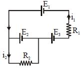
- 1The current $i_1$ and $i_2$ through the resistor $R_1 (= 10\,\Omega )$ and $R_2 (=30 \,\Omega )$ in the circuit diagram with $E_1 = 3\,V, E_2 = 3\,V$ and $E_3 = 2\,V$ are respectively:View Solution
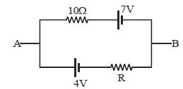
- 2In the following circuit if $V_A -V_B = 6\,V$ then the value of resistance $R$ (in $ohm$) is ............... $\Omega$View Solution
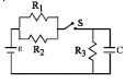
- 3The circuit shown in the figure consists of a battery of $emf$ $\varepsilon = 10 \,V$ ; a capacitor of capacitance $C = 1.0$ $ \mu F$ and three resistor of values $R_1 = 2$ $\Omega$ , $R_2 = 2$ $\Omega$ and $R_3 = 1$ $\Omega$ . Initially the capacitor is completely uncharged and the switch $S$ is open. The switch $S$ is closed at $t = 0.$View Solution
- 4The length of a potentiometer wire is $l$. $A$ cell of $\mathrm{emf}$ $E$ is balanced at a length $l/3$ from the positive end of the wire. If the length of the wire is increased by $l/2$. At what distance will the same cell give a balance point.View Solution
- 5Two equal resistances when connected in series to a battery, consume electric power of $60\,W.$ If these resistances are now connected in parallel combination to the same battery, the electric power consumed will be .............. $W$View Solution
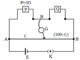
- 6In a meter bridge experiment, resistances are connected as shown in the following figure. The balancing length $l_1$ is $55\, cm$. Now, an unknown resistance $x$ is connected in series with $P$ and the new balancing length is found to be $75\, cm$. The value of $x$ isView Solution
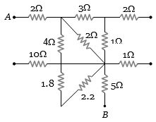
- 7What is the equivalent resistance between the points $A$ and $B$ of the network .................. $\Omega$View Solution
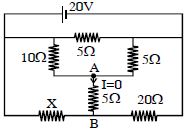
- 8In given circuit current through $AB$ is zero, then what will be the value of unknown resistance $'X'$ ............... $\Omega$View Solution
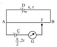
- 9In the figure, the potentiometer wire $AB$ of length $L$ and resistance $9r$ is joined to the cell $D$ of $\mathrm{emf}$ $\varepsilon$ and internal resistance $r$. The cell $C’s$ $\mathrm{emf}$ is $\varepsilon /2$ and its internal resistance is $2r$. The galvanometer $G$ will show no deflection when the length $AJ$ isView Solution
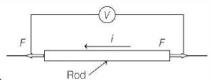
- 10As shown in the schematic below, a rod of uniform cross-sectional area $A$ and length $l$ is carrying a constant current $i$ through it and voltage across the rod is measured using an ideal voltmeter. The rod is stretched by the application of a force $F$. Which of the following graphs would show the variation in the voltage across the rod as function of the strain $\varepsilon$ when the strain is small. Neglect Joule heating.View Solution