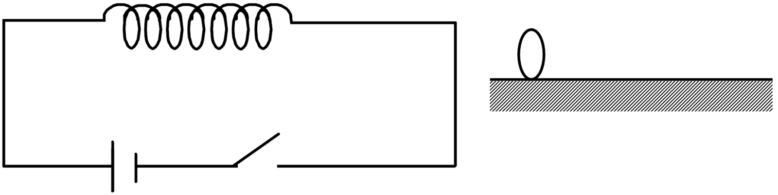
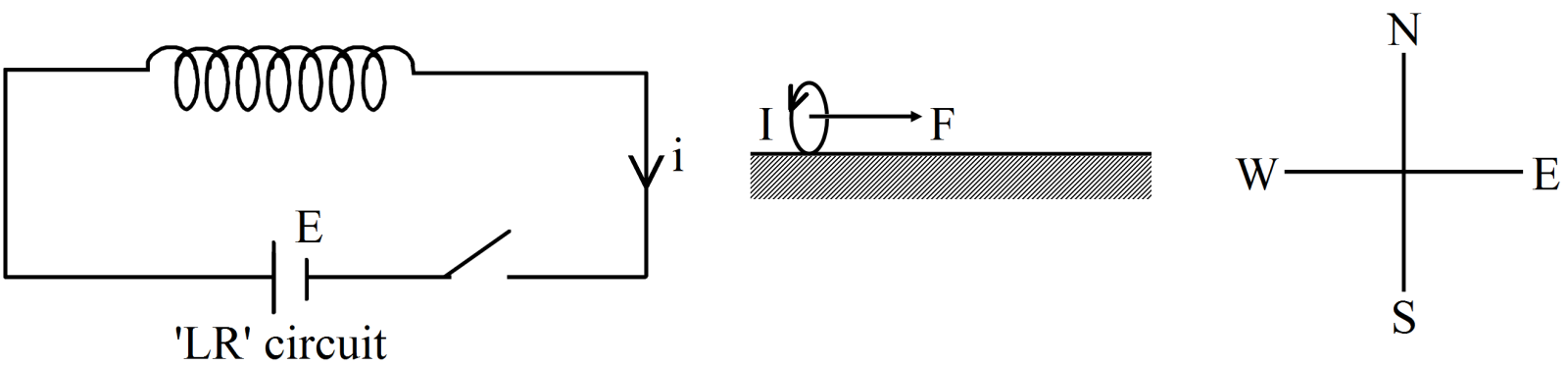
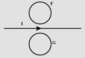
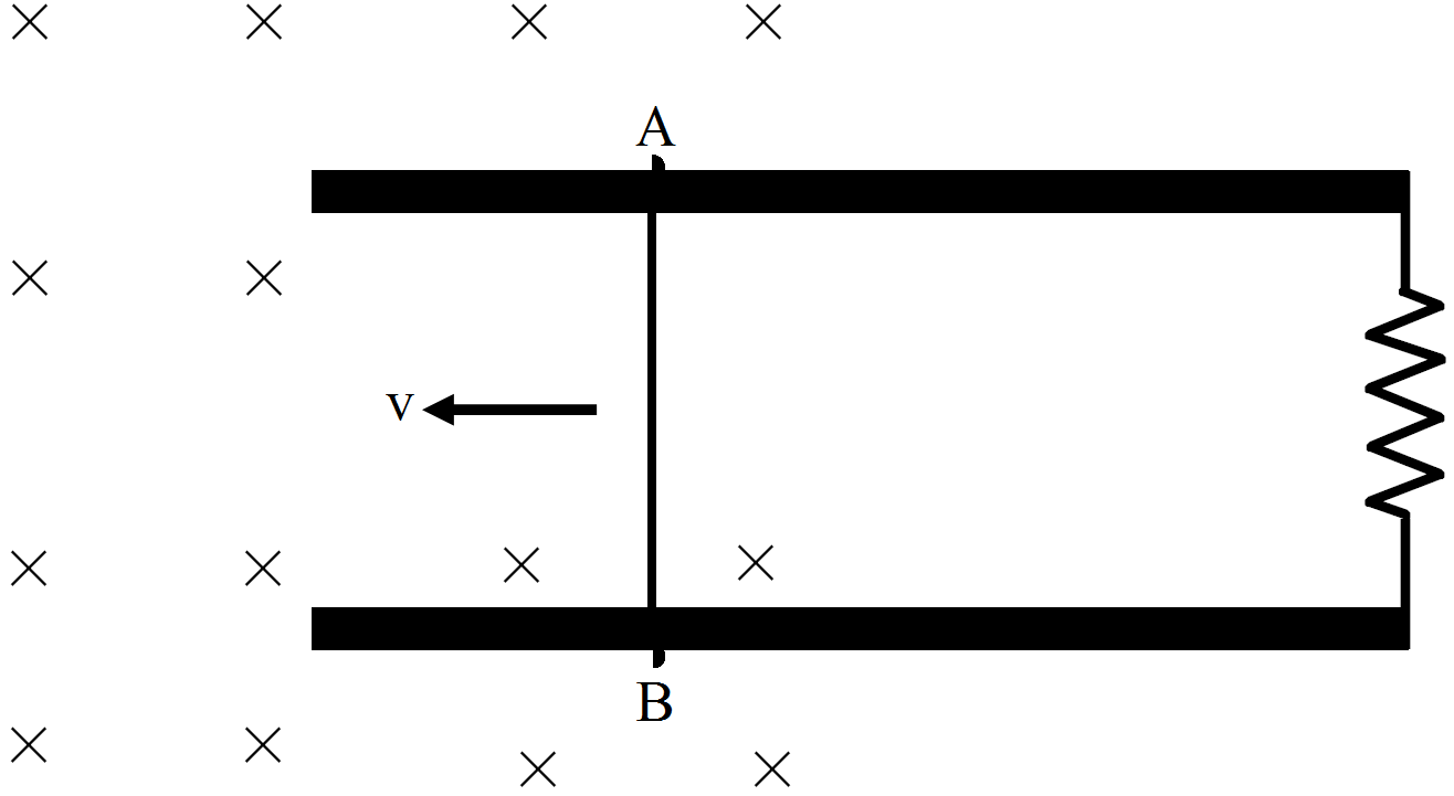
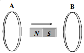
- ACurrent is induced only in A.
- BCurrent is induced only in B.
- CInduced currents in A and B are in the same directions
- ✓Induced currents in A and B are in opposite directions
50 questions · timed · auto-graded


Explanation:
$\text{emf},\in=\frac{\text{d}\phi}{\text{dt}}=\text{BL}^2\omega$
$\text{I}=\frac{\in}{\text{R}}=\frac{\text{BL}^2\omega}{\rho\frac{\text{L}}{\text{dt}}}=\frac{\text{BL}\omega\text{dt}}{\rho}$

Explanation:
Induced emf is AB is Bvl and Induced emf is DC is also Bvl.
Net emf in the closed circuit (loop) is zero.
So induced current in the loop is zero.
Explanation:
$\text{Max.emf = nAB}\omega$
$=50\times0.008\times0.05\times2000\frac{2\pi}{60}=\frac{4\pi}{3}\text{V}$
Explanation:
Self-inductance of a solenoid is given by $\text{L}=\frac{\mu_0\text{N}^2\text{A}}{1}$
where, N = number of turns in solenoid
l = length of the solenoid
A = area of one turn of solenoid.
The self-inductance of solenoid does not depend on current passing through it.
Explanation:
Flux linking the secondary coil due to current in primary = Mi1
induced emf in the secondary coils = rate of change of flux
$=\text{M}\frac{\triangle\text{i}_1}{\triangle\text{t}}$
$=5\times\frac{3-0}{0.001}$
$=15\text{kv}$

Explanation:
The magnetic field above the wire is out of the plane. This flux is decreasing and should be compensated by the current in the loop F and so the current in loop F will be anti-clockwise. For loop G the situation is opposite
Explanation:
emf = Blv
= 0.2 × 10-4 × 1 × 20
= 0.4mV
Explanation:
In self-induction,induced emf always opposes when the current in a coil is changing either increasing or decreasing.
So, A is true, B is false because when the current in a coil is increasing or decreasing, induced emf opposes it.
Explantion:
Induced emf in the axle = Blv
v - velocity of car
l - length of car
B - component of magnetic field perpendicular to both l and v.
That is B is the vertical component of magnetic field.
Vertical component of magnetic field is maximum at the poles.
Therefore emf induced in the axle will be maximum at the poles.
Explanation:
Induced emf is potential difference only, hence its unit is volt only.


Explanation:
induced emf = Blv = 12V. It is induced in the northward direction by right hand rule $\big(\text{emf}=\overrightarrow{\text{V}}\times\overrightarrow{\text{B}}\big)$
therefore if south end of pole has potential of 0V, north end will have a potential of 12V
Explanation:
As per Faradays law, EMF is always directly proportional to the rate of change of magnetic flux. Therefore, electromagnetic induction takes place whenever the magnetic flux passing through the object changes.
Explanation:
Henry (symbol H) is the SI derived unit of self-inductance.
Explanation:
Since there are no enclosed loops in a straight inductor the inductance of straight inductor is zero.
Explanation:
emf = rate of change of flux × number of turns $=\frac{12\times10^3\times10^{-8}}{0.2}\times100=0.06\text{V}$
emf = rate of change of flux × number of turns.
Explanation:
According to Faraday's Law when the magnetic flux linking a circuit changes, an electromotive force is induced in the circuit proportional to the rate of change of the flux linkage.
Explanation:
$\text{emf}=\text{L}\frac{\text{di}}{\text{dt}}$
$\text{emf}=\text{L}\frac{\triangle\text{i}}{\triangle\text{i}}$
So, $\text{L}=\text{emf}\times\frac{\triangle\text{t}}{\triangle\text{i}}$
$=32\times\frac{0.1}{8}$
$=0.4\text{H}$
Explanation:
In the field of electromagnetism, the term EMI stands for Electro Magnetic Induction.

Explanation:

When the switch is closed than a clock wise current pulse generated (Because initially current flow the terminal to negative terminal).
Due to Mutual Induction, current is generated in the loop. If circuit is open after some time. Dut to loop an anticlock wise current pulse generated in the circuit.
Explanation:
Force on a charge q in the rod = qvB
electric field inside the rod due to displacements of charges due to force by relative motion in magnetic field $=\frac{\text{emf}}{1}$
As the rod moves in constant velocity, net force of constituent charge q in the rod = 0
Therefore,
$\text{q}\frac{\text{emf}}{1}=\text{qvB}$
$\Rightarrow\text{emf}=\text{BIv}$
Explanation:
Initial flux through the coil, $=\text{BA}\cos\theta$
$=\text{BA}\cos0^\circ$ as the coil is perpendicular to magnetic field
= BA Wb
Final flux after the rotation,
$=\text{BA}\cos180^\circ$ the coil is rotated through 180°
=-BA Wb
Therefore, estimated value of the induced emf (E) as per Faraday's law is,
$\text{E}=\frac{\text{N}}{\text{t}}=\frac{\text{N}(\text{BA-(-BA}))}{\text{t}}=\frac{\text{2NBA}}{\text{t}}........(\text{i})$
Further, $\text{E}=\text{IR}=\frac{\text{QR}}{\text{t}}............(\text{ii})$
From (i) & (ii)
$\text{Q}=\frac{\text{2NBA}}{\text{R}}=\frac{2\times2000\times4\times10^{-5}\times500\times10^{-4}}{20}=4\times10^{-4}\text{C}$
Explanation:
lf e is the induced e.m.f. in the coil, then $\text{e}=\text{-L}\frac{\text{di}}{\text{dt}}$
$\therefore\text{L}=-\frac{\text{e}}{\frac{\text{di}}{\text{dt}}}$
Substituting values, we get $\text{L}=\frac{-8\times0.05}{-4}=0.1\text{H}$
Solution:
Key concept: The self inductance L of a solenoid depends on various factor like geometry and magnetic permeability of the core material.
$\text{L}=\mu_\text{r}\mu_0\text{n}^2\text{Al}$
where, $\text{n}=\frac{\text{N}}{\text{l}}$ (no. of turns per unit length)
The long solenoid of cross-sectional area A and length l, having A turns, filled inside of the solenoid with a material of relative permeability (e.g., soft iron, which has a high value of relative permeability) then its self inductance is $\text{L}=\mu_\text{r}\mu_0\text{n}^2\frac{\text{A}}{\text{l}}$.
So, the self inductance L of a solenoid increases as l decreases and A increases because L is directly proportional to area and inversely proportional to length.
Important point: The self and mutual inductance of capacitance and resistance depend on the geometry of the devices as well as permittivity/permeability of the medium.
Explanation:
Induction coil works on the principle of mutual induction that an emf or current is induced in the second coil if the magnetic flux due to first coil linked with the second coil changes.
Explanation:
Given,
L1 = 2mH
L2 = 8mH
The mutual inductance between coil is
$\text{M}=\sqrt{\text{L}_1\text{L}_2}$
$\text{M}=\sqrt{2\times8}=16\text{mH}$
$\text{M}=4\text{mH}$
Explanation:
Flux through a circular coil $\phi=\text{NBA}\cos\omega\text{t}$
Voltage required $\in=\frac{-\text{d}\phi}{\text{dt}}$
$\Rightarrow9=\text{NBA}\omega\sin\omega\text{t}$
$9=\frac{8\times10^{-5}\times\text{A}\times30\times2\pi\times2000}{60}$
$\text{A}=\frac{9\times10^5}{50\times10^3}=18\text{m}^2$
Explanation:
As per Faraday's law, the change in magnetic flux associated with coil produces an EMF in the coil. Whenever there is a change in magnetic flux associated with a coil, an EMF is induced in the coil. Magnetic flux is defined as the number of field lines passing normally through a given area. When magnetic flux changes, obviously, it means that, the number of magnetic field lines change.
Explanation:
On removal of load from the circuit, the circuit suddenly becomes an open circuit.
Thus $\frac{\text{di}}{\text{dt}}\rightarrow\infty$
For sparking, high voltage must appear across the open ends. This will happen only in case of an inductor as the voltage drop across the
inductor is $\text{L}\frac{\text{di}}{\text{dt}}$
Therefore, the circuit has high inductance.
Solution:
Key concept: Eddy Current: When a changing magnetic flux is applied to a bulk piece of conducting material, then circulating currents called eddy currents are induced in the material. Because the resistance of the bulk conductor is usually low, eddy currents often have large magnitudes and heat up the conductor.

A metal plate is getting heated when a DC or AC current is passed through the plate, known as heating effect of current. This current (called eddy current) is induced in the plate when a metal plate is subjected to a time varying magnetic field, i.e., the magnetic flux linked with the plate changes and eddy currents comes into existence which make the plate hot.
Explanation:
Current is induced in a coil when flux through the coil changes. The flux through the coil changes when a magnet moves relative to the coil and coil is at rest relative to the magnet.
Explanation:
As the copper wire cuts the magnetic lines of force, the free charges in the wire will experience a force and will get displaced. This displacement of charges in the wire creates a potential difference and hence emf is induced.
Explanation:
The magnetic force due to the conducting rod of length l and mass m is,
Fm = i(l × B), the angle between l and B is 90°.
Fm = ilB
The horizontal component of Fm is
$\text{F}=\text{F}_\text{m}\cos\theta$
The force due to gravity is F = mg and its horizontal component is
$\text{F}''=\text{mg}\sin\theta$
From the above figure,
$\text{mg}\sin\theta=\text{ilB}\cos\theta$
$\text{B}=\frac{\text{mg}}{\text{il}}\tan\theta$
Explanation:
$\text{emf}=\text{L}\frac{\text{di}}{\text{dt}}$
$\frac{\text{di}}{\text{dt}}=\frac{\text{emf}}{\text{L}}$
$=\frac{8}{0.1}$
$=\frac{80\text{A}}{\text{s}}$
Explanation:
The transformer does this by linking together two or more electrical circuits using .The two coil windings are not electrically connected but are only .The difference in voltage between the primary and the secondary windings is .Also this induced voltage has the same frequency as the primary winding voltage.The current induced in primary circuit is of same nature as in secondary circuit with differences in amplitude only.A transformer is a static electrical device that transfers electrical energy between two or more circuits through electromagnetic induction.

Explanation:
Current will be zero at t = 0+
if the current is zero magnetic field will be zero at t = 0+
power delivered will be zero at t = 0+
The EMF induced will be equal to the applied voltage in the inductor to oppose the current.
Explanation:
Coefficient of mutual induction will be the ratio of the flux linked with the secondary coil and the current primary coil.
$\text{M}=\frac{200}{5}=40\text{H}$

Explanation:

$\text{e}=-\text{L}\frac{\text{di}}{\text{dt}}$
Current flow in the CKt is clock wise direction, due to Mutual Induction current flow in the loop anti clockwise direction. The net force applied on the loop in east direction. So we can say that the ring will move away from the solenoid.
Explanation:

Emf at both end is same $=\frac{1}{8}\text{Bwl}^2$
So the potential difference between the two ends of therod is zero.
Explanation:
The flux linked with two coils will depend upon the angle between the two coils. If their planes are parallel, then magnetic flux from one would completely pass through the other. If the planes are perpendicular, no flux due to any of the coils would flow through the other.
The size of the two coils may be different which will affect the number of lines crossing the coil. The medium, if magnetic, will concentrate the field lines. Thus, all parameters would affect the inductance between them.

Explanation:

E = Bvl
If the wire AB is replaced by a semicircular wire, the magnitude of the induced current will be same. Because it is depend on the velcoty & lenght of the wire.
Explanation:
Inductance is the property of a conductor by which a change in current flowing through it induces (creates) a voltage (electromotive force) in both the conductor itself (self-inductance) and in any nearby conductors (mutual inductance). By Lenz's law the induced voltage opposed the the change in current. Hence inductance is defined as.
$\text{L}=\Big(-\frac{\text{dI}}{\text{dt}}\Big)$
Explanation:
Upon connecting to the AC source, a current starts to flow in the coil P. This current induces a current in the galvanometer coil Q due to mutual inductance because of the flux linkages. This induced current causes a deflection in the galvanometer.
Explanation:
Induced emf is given by:
ε = Bvl
On putting the values we get
= 5 × 10-5 × 1.50 × 2
= 0.15 mV
Explanation:
$\text{emf}=-\frac{\text{d}\phi}{\text{dt}}=-12\text{t}+5$
$\text{Current}=-\frac{\text{emf}}{10}=-1.2\text{t}+0.5$
$\text{Current at t}=0.25\text{s},$
$=1.2\times0.25+0.5=0.2\text{A}$

Explanation:
Electromagnetic induction is the production of current by relative motion between a magnet and a coil.The phenomenon of producing electric current in a conductor by moving it perpendicular to a magnetic field or vice -versa, is called electro magnetic induction.