Questions

4 Marks Questions

Take a timed test

6 questions · self-marked practice — reveal the answer and mark yourself.

Question 14 Marks
Explain full wave rectification with the help of proper circuit diagram and draw the waveform of input and output voltage.
Answer

Image

→ The circuit diagram of the full-wave rectifier is shown in the figure. In full wave rectifier, two $p-n$ junction diodes are used.
→ In this type of rectifier, the rectified output voltage is obtained during both the positive as well as negative half of ac cycle. Hence, it is known as full-wave rectifier.
→ As shown in fig., the $p$-side of the two diodes are connected to the ends of the secondary of the transformer. The $n$-side of the diodes are connected together and the output is taken between this common point of diodes and the mid-point of the secondary of the transformer. So for a full wave rectifier the secondary of the transformer is provided with a centre tapping and so it is called centre-tap transformer.
→ As can be seen from fig. (c), the voltage rectified by each diode is only half the total secondary voltage. Each diode rectifies only for half the cycle, but the two do so for alternate cycles. Thus the output between their common terminals and the centre tap of the transformer becomes a full-wave rectifier output.
→ Suppose the input voltage to $A$ with respect to centre tap at any instant is positive. At that instant, voltage $B$ being out of phase should be negative. In this case, diode $D_1$ gets forward biased and conducts, while $D_2$ gets reverse biased and does not conduct. Hence, as shown in fig. c, output current is obtained between two terminals of $R_L$ during this half-cycle.
→ During the other half-cycle, voltage at $A$ is negative and voltage at $B$ is positive. In this case diode $D_1$ is in reverse bias condition and $D_2$ is in forward bias. Hence, in this part of cycle, $D_2$ conducts and output voltage is obtained.
→ Thus, we get output voltage during both positive as well as negative half of the cycle.
View full question & answer
Question 24 Marks
How long can an electric lamp of 100 W be kept glowing by fusion of 2.0 kg of deuterium? Take the fusion reaction as
\[{ }_1^2 H+{ }_1^2 H \longrightarrow{ }_2^3 He+n+3.27 MeV\]
Answer
→ atomic weight of deuteron $=2 g / mol$
Mass of deuteron No. of atoms
$
\begin{array}{l}
2 g 6.023 \cdot 10^{23} \\
\therefore 2000 g(?)
\end{array}
$
→ No. of atoms
$
\begin{array}{l}
N=\frac{2000 \times 6.023 \times 10^{23}}{2} \\
\therefore N=6.023 \cdot 10^{26}
\end{array}
$
→ When two atoms of deuteron fuse, the energy released $=3.27 MeV$
$\therefore$ The energy released by fusion of N atoms
$
\begin{array}{l}
E=\frac{\frac{N \times 3.27}{2} MeV}{} \\
E=\frac{6.023 \times 10^{26} \times 3.27 \times 10^6 \times 1.6 \times 10^{-19}}{2} \\
\therefore E=15.75 \cdot 10^{13} J
\end{array}
$
→ Power of electric lamp $=100 W$. It means the energy consumed by the lamp per second $=100 J$
$
\begin{array}{l}
\therefore \text { time required to consumed } 15.75 \cdot 10^{13} J \\
t=\frac{15.75 \times 10^{13}}{100} \\
\therefore t=15.75 \cdot 10^{11} s \\
\therefore t=\frac{15.75 \times 10^{11}}{3.154 \times 10^7} \\
\therefore t=4.99 \cdot 10^4 \text { years }
\end{array}
$
→ Thus, an electric bulb can glow for about 50,000 years.
View full question & answer
Question 34 Marks
Draw the ray diagram for the formation of image by a compound microscope and obtain the formula for magnification.
View full question & answer
Question 44 Marks
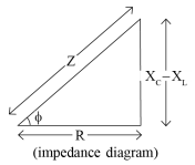
A sinusoidal voltage of peak value 283 V and frequency 50 Hz is applied to a series LCR circuit in which $R =3 \Omega, L=25.48 mH$ and $C =796 \mu F$. Find
(a) the impedance of the circuit
(b) the phase difference between the voltage across the source and the current,
(c) the power dissipated in the circuit and
(d) the power factor.
Answer

$
\begin{array}{l}
V_m=283 V \\
R=3 \Omega \\
C=796 \propto F \\
v=50 Hz \\
L=25.48 mH
\end{array}
$
→ (a) Impedence of the circuit ( $Z$ ),
→ Inductive reactance $\left( X _{ L }\right)$
$
\begin{array}{l}
X_{L}=\omega L=2 \pi v L \\
\therefore X_{L}=2 \times 3.14 \times 50 \times 25.48 \times 10^{-3} \\
\therefore X_{L}=8000.72 \times 10^{-3} \\
\therefore X_{L}=8 \Omega
\end{array}
$
→ Capacitive reactance ( $X _{ C }$ )
$
\begin{array}{l}
X_{C}=\frac{1}{\omega C}=\frac{1}{2 \pi v C} \\
\therefore X_{C}=\frac{1}{2 \times 3.14 \times 50 \times 796 \times 10^{-6}} \\
\therefore X_{C}=\frac{1000000}{249944} \\
\therefore X_{C}=4 \Omega
\end{array}
$
$
\begin{array}{l}
→ Z=\sqrt{R^2+\left(X_{C}-X_{L}\right)^2} \\
\therefore Z=\sqrt{3^2+(4-8)^2} \\
\therefore Z=5 \Omega
\end{array}
$
(b) Phase difference ( $\varphi$ )
Image

$
\begin{array}{l}
\tan \varphi=\frac{X_{C}-X_{L}}{R} \\
\tan \varphi=\frac{4-8}{3} \\
\tan \varphi=-\frac{4}{3} \\
\tan \varphi=-1.3333 \\
\varphi=-53.1^{\circ} \\
(\because \tan (-\theta)=-\tan \theta)
\end{array}
$
Note : Here $\varphi$ is negative. So the current in the circuit is lagging behind the voltage between two terminals of the source.
(c) Power dissipated in the circuit :
$
P=I^2 R
$
But $I =\frac{ I _m}{\sqrt{2}}$
$
\therefore I=\frac{V_m}{Z \sqrt{2}}
$
$
\therefore P=\frac{V_m^2}{Z^2(2)} \cdot R
$
$
\therefore P=\frac{(283)^2 \times 3}{25 \times 2}
$
$
\therefore P=4800 W
$
(d) Power factor,
$
\begin{array}{l}
\cos \varphi=\cos \left(-53.1^{\circ}\right)(\because \cos (-\theta)=\cos \theta) \\
=\cos 53.1^{\circ} \\
=0.6
\end{array}
$
View full question & answer
Question 54 Marks
As shown in figure, resistances are connected in the four arms of a Wheatstone bridge.
Image

A galvanometer of $15 \Omega$ resistance is connected across BD. Calculate the current through galvanometer when a potential difference of 10 V is maintained across AC.
Answer
→ Applying kirchhoff's second law to closed loop B - A - D - B
$
\begin{array}{l}
100 I_1-60 I_2+15 I_{g}=0 \\
\therefore 20 I_1-12 I_2+3 I_{g}=0 ...(1)
\end{array}
$
→ Applying Kirchhoff's second law to closed loop B - C - D - B
$
\begin{array}{l}
-10\left(I_1-I_g\right)+5\left(I_2+I_g\right)+15 I_g=0 \\
\therefore-2\left(I_1-I_g\right)+I_2+I_g+3 I_g=0 \\
\therefore-2 I_1+2 I_g+I_2+I_g+3 I_g=0 \\
\therefore-2 I_1+I_2+6 I_g=0 \\
\therefore 2 I_1-I_2-6 I_g=0 \ldots(2)
\end{array}
$
→ Applying Kirchhoff's second law to closed loop A-D-C-E-A
$
\begin{array}{l}
-60 I_2-5\left(I_2+I_g\right)+10=0 \\
\therefore-60 I_2-5 I_2-5 I_g+10=0 \\
\therefore-65 I_2-5 I_g+10=0 \\
\therefore-5\left(13 I_2+I_g-2\right)=0 \\
\therefore 13 I_2+I_g=2 \ldots \text { (3) }
\end{array}
$
→ Multiplying equation (2) by 10 and subtracting from equation (1),
$
\begin{aligned}
\therefore & 20 I_1-12 I_2+3 I_g=0 \\
& 20 I_1-10 I_2-60 I_g=0 \\
& -\quad+\quad+ \\
- & 2 I_2+63 I_g=0 \\
- & 2 I_2=-63 I_g \\
I_2= & \frac{63}{2} I_g \ldots(4)
\end{aligned}
$
→ Using equation (4) in equation (3)
$
\begin{array}{l}
\therefore 13\left(\frac{63}{2}\right)_{I_g}+I_g=2 \\
\therefore \frac{819 I_g+2 I_g}{2}=2 \\
\therefore 821 I_g=4 \\
\therefore I_g=\frac{4}{821}=4.87 mA
\end{array}
$
View full question & answer
Question 64 Marks
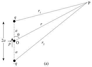
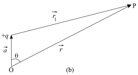
Derive the formula for electric potential due to an electric dipole at a point having position vector $\bar{r}$ with respect to the mid-point of the dipole and discuss the electric potential on
(a) equator
(b) axis
Answer

Image

→ As shown in fig. point $P$ is given at a distance ' $r$ ' from the midpoint ' $O$ ' of electric dipole and at an angle $\theta$ (with the electric dipole moment $\vec{p}$ ).
We want to find electric potential at this point $P$.
→ Electric potential at point P due to charge $+q$,
$
V_1=\frac{1}{4 \pi \varepsilon_0} \cdot \frac{q}{r_1}
$
→ Electric potential at point $P$ due to charge $-q$,
$
\begin{array}{l}
V_2=\frac{1}{4 \pi \varepsilon_0} \frac{(-q)}{r_2} \\
=-\frac{1}{4 \pi \varepsilon_0} \cdot \frac{q}{r_2}
\end{array}
$
→ Total electric potential at point P as per super position principle,
$
\begin{array}{l}
V=V_1+V_2 \\
\therefore V=\frac{1}{4 \pi \varepsilon_0} \cdot \frac{q}{r_1}-\frac{1}{4 \pi \varepsilon_0} \cdot \frac{q}{r_2} \\
\therefore V=\frac{q}{4 \pi \varepsilon_0}\left(\frac{1}{r_1}-\frac{1}{r_2}\right)
...(1)\end{array}
$
→ As shown in the figure (a), position vector of point P with respect to origin O is $\vec{r}$.
Position vector of point $P$ with respect to
$+q$ is $\vec{r}_1$.
Position vector of point $P$ with respect to
$-q$ is $\overrightarrow{r_2}$.
Image

→ From figure (b),
$
\begin{array}{l}
\vec{r}=\vec{a}+\vec{r}_1 \\
\therefore \vec{r}_1=\vec{r}-\vec{a} \\
\therefore r_1^2=r^2+a^2-2 r a \cos \theta(\theta \text { is angle between } \vec{r} \text { and } \vec{a}) \\
\therefore r_1^2=r^2\left(1+\frac{a^2}{r^2}-\frac{2 a \cos \theta}{r}\right)
\end{array}
$
→ But value of $\frac{a^2}{r^2}$ is very less for $r \gg a$, so it can be neglected from equation.
$
\begin{array}{l}
\therefore r_1^2=r^2\left(1-\frac{2 a \cos \theta}{r}\right) \\
\therefore r_1=r^{\left(1-\frac{2 a \cos \theta}{r}\right)^{\frac{1}{2}}} \\
\therefore \frac{1}{r_1}=\frac{1}{r}\left(1-\frac{2 a \cos \theta}{r}\right)^{-\frac{1}{2}}
\end{array}
$
→ Using the binomial theorem to expand the equation,
$
\frac{1}{r_1}=\frac{1}{r}\left[1-\left(-\frac{1}{2}\right) \frac{2 a \cos \theta}{r}+\ldots . .+ \text { other higher order terms of } \frac{2 a \cos \theta}{r}\right)
$
→ But the terms having more than 1 power will be very small and hence they can be neglected in the above equation,
$
\begin{array}{l}
\therefore \frac{1}{r_1}=\frac{1}{r}\left(1+\frac{1}{2} \cdot \frac{2 a \cos \theta}{r}\right) \\
\therefore \frac{1}{r_1}=\frac{1}{r}\left(1+\frac{a \cos \theta}{r}\right)
...(2)\end{array}
$
→ Similarly,
$
\frac{1}{r_2}=\frac{1}{r}\left(1-\frac{a \cos \theta}{r}\right)
...(3)$
can be derived.
→ Substituting values of $\frac{1}{r_1}$ and $\frac{1}{r_2}$ from equation (2) and (3) in equation (1),
$
\begin{array}{l}
\therefore V=\frac{q}{4 \pi \varepsilon_0}\left[\frac{1}{r}\left(1+\frac{a \cos \theta}{r}\right)-\frac{1}{r}\left(1-\frac{a \cos \theta}{r}\right)\right] \\
\therefore V=\frac{q}{4 \pi \varepsilon_0 r}\left(1+\frac{a \cos \theta}{r}-1+\frac{a \cos \theta}{r}\right) \\
\therefore V=\frac{q}{4 \pi \varepsilon_0 r} \cdot \frac{2 a \cos \theta}{r} \\
\therefore V=\frac{1}{4 \pi \varepsilon_0} \cdot \frac{p \cos \theta}{r^2}
...(4)\end{array}
$
$(\because p=2 a q$ Electric dipole moment)
$
\therefore V=\frac{1}{4 \pi \varepsilon_0} \cdot \frac{\vec{p} \cdot \hat{r}}{r^2}(r \gg a) \ldots(5)(\because p \cos \theta=\vec{p} . \hat{r})
$
Where, $\hat{r}$ is the unit vector along the position vector $\vec{r}$.
OR
$
V=\frac{1}{4 \pi \varepsilon_0} \cdot \frac{\vec{p} \cdot \vec{r}}{r^3} \ldots(6)
$
→ Equations (4), (5) and (6) show electric potential of dipole.
View full question & answer
4 Marks Questions - Physics STD 12 Science Questions - Vidyadip