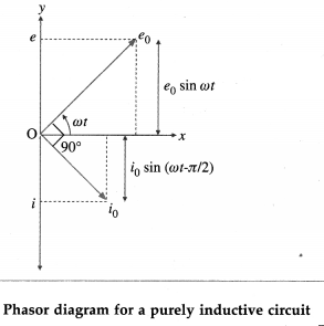
Questions

Answer the following in Brief

Take a timed test

25 questions · self-marked practice — reveal the answer and mark yourself.

Question 13 Marks
What is the natural frequency of $LC$ circuit ? What is the reactance of this circuit at this frequency
Answer
The natural frequency of LC circuit is $\frac{1}{2 \pi \sqrt{L C}}$, where $L$ is the inductance and $C$ is the capacitance. The reactance of this circuit at this frequency is
$ \frac{1}{2 \pi f C-\frac{1}{2 \pi f L}}=\frac{1}{\frac{2 \pi C}{2 \pi \sqrt{L C}}-\frac{1}{\frac{2 \pi L}{2 \pi \sqrt{L C}}}}$
$=\frac{1}{\sqrt{\frac{C}{L}}-\sqrt{\frac{C}{L}}}=\frac{1}{\text { zero }}=\infty $
View full question & answer
Question 23 Marks
What is wattless current ?
Answer
The current that does not lead to energy consumption, hence zero power consumption, is called wattless current.
In the case of a purely inductive circuit or a purely capacitive circuit, average power consumed over a complete cycle is zero and hence the corresponding alternating current in the circuit is called wattless current.
[Note : In this case, the power factor is zero.]
View full question & answer
Question 33 Marks
The total impedance of a circuit decreases when a capacitor is added in series with L and R. Explain why ?
Answer
For an LR circuit, the impedance,
$Z _{ LR }=\sqrt{R^2+X_{ L ^{\prime}}^2}$, where $X _{ L }$ is the reactance of the inductor.
When a capacitor of capacitance $C$ is added in series with $L$ and $R$, the impedance,
$Z_{ LCR }=\sqrt{R^2+\left(X_{ L }-X_{ C }\right)^2}$ because in the case of an inductor the current lags behind
the voltage by a phase angle of $\frac{\pi}{2}$ rad while in the case of a capacitor the current leads the voltage by a phase angle of $\frac{\pi}{2}$ rad. The decrease in net reactance decreases the total impedance $\left(Z_{L C R}<Z_{L R}\right)$.
View full question & answer
Question 43 Marks
An electric lamp is connected in series with a capacitor and an AC source is glowing with a certain brightness. How does the brightness of the lamp change on increasing the capacitance ?
Answer
Impedance, $Z=\sqrt{R^2+\frac{1}{\omega^2 C^2}}$, where $R$ is the resistance of the lamp, $w$ is the angular frequency of $A C$ and $C$ is the capacitance of the capacitor connected in series with the $A C$ source and the lamp. When $C$ is increased, decreases. Hence, $Z$ increases.
Power factor, $\cos \Phi=\frac{R}{Z}$
As $Z$ increases, the power factor decreases.
Now, the average power over one cycle,
$ P _{ av }= v _{ rms } i _{ rms } \cos \Phi$
$= V _{ rms }\left(\frac{V_{ rms }}{Z}\right) \cos \Phi$
$=\frac{V_{\text {rms }}^2}{ Z } \cos \phi $
$\therefore P _{ av }$ decreases as $Z$ increases and $\cos \Phi$ decreases.
As the current through the lamp $\left(\frac{V_{\text {rms }}}{Z}\right)$ decreases, the brightness of the lamp will
View full question & answer
Question 53 Marks
An ac voltage of rms value $1 V$ is applied to a parallel combination of inductor $L =10 mH$ and capacitor $C =4 \mu F$. Calculate the resonant frequency and the current through each branch at resonance.
Answer
Data : $e _\text{ rms }=1 V , L =10 mH =10^{-2} H , $
$C =4 \mu F =4 \times 10^{-6} F$
$(i)$ Resonant frequency,
$f_{ r }=\frac{1}{2 \pi \sqrt{L C}}=\frac{1}{2 \times 3.142 \times \sqrt{10^{-2} \times 4 \times 10^{-6}}}$
$=795.7 Hz$
$(ii)$ At resonance, the currents through the inductor and capacitor are in exact antiphase but equal in magnitude $i _{ L }= i _{ C }$.
$\therefore i _{ C }=\frac{e_{ mms }}{X_{ C }}$
$=\left(2 \pi f _{ r } C \right) e _\text{ rms }$
$=\left(2 \times 3.142 \times 795.7 \times 4 \times 10^{-6}\right)(1)=0.02 A$
View full question & answer
Question 63 Marks
An ac circuit consists of an inductor of inductance $125 mH$ connected in parallel with a capacitor of capacity $50 \mu F$. Determine the resonant frequency.
Answer
Data : $L =125 mH =0.125 H , C =50 \mu F =50 \times 10^{-6} F$
Resonant frequency,
$
\begin{aligned}
f_{ r } & =\frac{1}{2 \pi \sqrt{L C}} \\
& =\frac{1}{2 \times 3.142 \times \sqrt{0.125 \times 50 \times 10^{-6}}} \\
& =\frac{1000}{6.284 \times \sqrt{6.25}} \text { } \\
& =\frac{1000}{6.284 \times 2.5} \\
= & 63.65 Hz
\end{aligned}
$
View full question & answer
Question 73 Marks
In a parallel resonant circuit, the inductance of the coil is $3 mH$ and resonant frequency is $1000 kHz$. What is the capacitance of the capacitor in the circuit?
Answer
Data : $L=3 mH =3 \times 10^{-3} Hz , f _{ r }=1000 kHz =1000 \times 10^3=10^6 Hz$
$
f_{ r }=\frac{1}{2 \pi \sqrt{L C}} \quad \therefore f_{ f }^2=\frac{1}{4 \pi^2 L C}
$
$\therefore$ Capacitance,
$
\begin{aligned}
& C=\frac{1}{4 \pi^2 L f_t^2}=\frac{1}{4 \times(3.142)^2 \times 3 \times 10^{-3} \times 10^{12}} \\
= & 8.441 \times 10^{-12} F \text { or } 8.441 pF
\end{aligned}
$
View full question & answer
Question 83 Marks
An ac circuit consists of a resistor of 50 and an inductor of $10 mH$ connected In series with a $50 V$
(peak)/50 Hz supply. What capacitance should be connected in series with the circuit to obtain maximum current? What will be the maximum current?
Answer
Data: $R=50 \Omega, L=10 mH =10 \times 10^{-3} H , e_0=50 V , f =50 Hz$
(i) Maximum current is obtained at resonance.
The condition for resonance is
$
\begin{aligned}
X_{ L } & =X_{ C } \\
\therefore \omega L & =\frac{1}{\omega C } \quad \therefore 2 \pi f L=\frac{1}{2 \pi f C} \\
\therefore C & =\frac{1}{4 \pi^2 f^2 L}=\frac{1}{4 \times(3.142)^2 \times(50)^2 \times 10 \times 10^{-3}} \\
& =1.013 \times 10^{-3} F =1013 \mu F
\end{aligned}
$
(ii) At resonance, $Z=R$
$\therefore$ Maximum current,
$
i_0=\frac{e_0}{Z}=\frac{e_0}{R}=\frac{50}{5}=10 A
$
View full question & answer
Question 103 Marks
What is a rejector circuit? State its use.
Answer
A rejector circuit is a parallel LC resonant circuit used in communications and broadcasting as well as filter circuits to selectively reject a signal of a certain frequency.
The resonance curve of a parallel resonant circuit with a finite resistance of its inductor windings exhibits a sharp minimum at a certain frequency called the resonant frequency $f_r$. For an alternating signal of this frequency, the impedance of the circuit is maximum and the current is minimum. That is, the circuit has a selective property to reject a signal of frequency $f _{ r }$ while passing those of other frequencies.
Use : A rejector circuit is used at the output stage of a radiowave transmitter.
View full question & answer
Question 113 Marks
State the characteristics of a parallel LC AC resonance circuit.
Answer
Characteristics of a parallel LC AC resonance circuit:
1. Resonance occurs when inductive reactance $\left(X_L=2 \pi f L\right)$ equals capacitive reactance $\left(X_c=\frac{1}{2 \pi f C}\right)$
Resonant frequency, $f _{ r }=\frac{1}{2 \pi \sqrt{L C}}$
2. Impedance is maximum.
3. Current is minimum.
4. The circuit rejects $f _{ r }$ but allows the current to flow for other frequencies. Hence, it is called a rejector circuit.
View full question & answer
Question 123 Marks
State the characteristics of a series LCR AC resonance circuit.
Answer
Characteristics of a series LCR AC resonance circuit:
1. Resonance occurs when inductive reactance $\left(X_L=2 \pi f L\right)$ equals capacitive reactance $j$ $\left(X_C=\frac{1}{2 \pi f C}\right)$. Resonant frequency, $f_r=\frac{1}{2 \pi \sqrt{L C}}$.
2. Impedance is minimum and the circuit is purely resistive.
3. Current is maximum.
4. Frequencies, other than the resonant frequency $\left( f _{ r }\right)$ are rejected. Only $f _{ r }$ is accepted. Hence, it is called the acceptor circuit.
View full question & answer
Question 133 Marks
A circuit has a resistance and a reactance, each equal to $100 \Omega$ Find its power factor. If the rms value of the applied voltage is $200 V$, what is the average power consumed by the circuit?
Answer
Data : $R=100 \Omega, X=100 \Omega, V_{\text {rms }}=200 V$
$
\begin{aligned}
Z & =\sqrt{R^2+X^2}=\sqrt{2 R^2}=R \sqrt{2}=100 \sqrt{2} \\
& =141.4 \Omega \quad \text { }
\end{aligned}
$
$\therefore$ Power factor, $\cos \phi=\frac{R}{Z}=\frac{100}{141.4}=0.7071$
$
i_{\text {rms }}=\frac{e_{\text {rms }}}{Z}=\frac{200}{141.4}=1,415 A
$
$\therefore$ The average power, $P = e _{ rms } i _{ rms } \cos \Phi$
$
=200 \times 1.415 \times 0.7071=200 W
$
View full question & answer
Question 143 Marks
An alternating emf $e=200 \sin \omega t$ (in volt) is connected to a $1000 \Omega$ resistor. Calculate the rms current through the resistor and the average power dissipated in it in one cycle.
Answer
Data: $e =200 \sin \omega t V , R =1000 \Omega$
The equation of a sinusoidally alternating emf is $e=e_0 \sin \omega t_s$ where $e_0$ is the peak value of the emf.
Comparing the given expression with this, we get
$\therefore$ Peak current, $i _0=\frac{e_0}{R}=\frac{200}{1000}=0.2 A$
$\therefore$ rms current, $i _{ rms }=\frac{i_0}{\sqrt{2}}=\frac{0.2}{\sqrt{2}}=0.1414 A$
The average power dissipated in the resistor in one cycle,
$
P_{ av }= e _{ rms } i _{ rms }=\frac{e_0 i_0}{2}=\frac{200 \times 0.2}{2}=20 W
$
View full question & answer
Question 153 Marks
State the expression for the average power consumed over one cycle in the case of a series $\text{LCR}\ \  AC$ circuit. What happens if the circuit is purely
$(i)$ resistive
$(ii)$ inductive
$(iii)$ capacitive?
Answer
Average power consumed over one cycle in the case of a series $\text{LCR} \  \ AC$ circuit,
$P_{ av }=e_\text{ rms } i_{\text {rms }} \frac{R}{Z}$
$=e_{\text {rms }}\left(\frac{e_{\text {rms }}}{Z}\right)\left(\frac{R}{\bar{Z}}\right)$
$=\frac{R\left(e_\text{ rms }\right)^2}{Z^2}$
$=\frac{R\left(e_\text{ rmms }\right)^2}{R^2+\left( X _{ L }- X _{ C }\right)^2} .$
Particular cases : $(i) P_{ av }=\frac{e^2 \text { rms }}{R}$
$(ii) P_{\text {av }}=0$
$(iii) P_{ av }=0$.
View full question & answer
Question 163 Marks
An alternating emf with $e _\text{ rms }=60 V$ is applied to a series $CR$ circuit with $R =100 \sqrt{3} \Omega$ and capacitive reactance $100 V 3 Q$. What is the average power consumed over one cycle?
Answer
The average power consumed over one cycle
$=e_\text{ rms } i_\text{ rms } \frac{R}{ Z }=e_\text{ rms }\left(\frac{e_\text{ rmms }}{Z}\right) \frac{R}{Z}$
$=\frac{\left(e_\text{ rms }\right)^2 R}{Z^2}$
$=\frac{e_\text{ rms }^2 R}{R^2+X_{ C }^2}$
$=\frac{(60)(60)(100)}{(100)^2+(100 \sqrt{3})^2}$
$=\frac{(36)(100)^2}{(100)^2[1+3]}$
$=\frac{36}{4}=9 W \text {. }$
View full question & answer
Question 173 Marks
A $20 \mu F$ capacitor is connected in series with a $25 \Omega$ resistor and a source of alternating emf, $240 V$ (peak) $/ 50 Hz$. Calculate the capacitive reactance, circuit impedance and the maximum current in the circuit.
Answer
Data : $C =20 \mu F =20 \times 10^{-6} F , k =25 \Omega_r e _0=240 V , f =50 Hz$
(i) Capacitive reactance,
$
\begin{aligned}
X_C & =\frac{1}{\omega C}=\frac{1}{2 \pi f C} \\
& =\frac{1}{2 \times 3.142 \times 50 \times 20 \times 10^{-6}}=159.1 \Omega
\end{aligned}
$
(ii) Impedance,
$
Z=\sqrt{\left(X_C\right)^2+R^2}=\sqrt{(159.1)^2+(25)^2}=161.1 \Omega
$
(iii) Maximum current,
$
i_0=\frac{e_0}{Z}=\frac{240}{161.1}=1.49 A
$
View full question & answer
Question 183 Marks
An alternating emf is applied to a series combination of an inductor and a resistor $(R=100\Omega).$ If the impedance of the circuit is $100 \sqrt{2} \Omega,$ what is the phase difference between the emf and the current?
Answer
Data : $R=100 \Omega, Z=100 \sqrt{2} \Omega$
$\cos \phi=\frac{R}{Z}=\frac{100}{100 \sqrt{2}}=\frac{1}{\sqrt{2}}$
$\phi=\cos ^{-1}\left(\frac{1}{\sqrt{2}}\right)=\pi / 4 \text{ rad} =45^{\circ}$
This is the phase difference between the $\text{emf}$ and the current.
View full question & answer
Question 193 Marks
An alternating emf of frequency $50 Hz$ is applied a series combination of an inductor $( L =2H)$ and a resistor $(R=100 \Omega)$. What is the impedance of the circuit?
Answer
Data : $f=50 Hz , L =0.2 H , R =100 \Omega$
The inductive reactance, $X_L=2 \pi f L$
$=2(3.142)(50)(0.2)=62.84 \Omega$
The impedance of the circuit, $Z=\sqrt{R^2+X_L^2}$
$=\sqrt{(100)^2+(62.84)^2}$
$=\sqrt{10000+3949}=\sqrt{13949}$
$=118.1 \Omega$
View full question & answer
Question 203 Marks
What is meant by the term impedance? State the formula for it in the case of an LCR series circuit.
Answer
In an AC circuit containing resistance and inductance and / or capacitance, the effective resistance offered by the circuit to the flow of current is called impedance. It is denoted by $Z$. For an LCR series circuit,
$Z=\sqrt{R^2+\left(\omega L-\frac{1}{\omega C}\right)^2}$ where
$\omega=2 \pi f$ is the angular frequency and $f$ is the frequency of $A C$.
[Note: Here, in the absence of a capacitor.
$Z=\sqrt{R^2+\omega^2 L^2}$, and in the absence of an inductor,
$\left.Z =\sqrt{R^2+\frac{1}{\omega^2 C^2}}\right]$.
View full question & answer
Question 213 Marks
How does a pure inductor behave when the frequency of the applied alternating emf is
(i) very high
(ii) very low?
Answer
Inductive reactance $=2 \pi fL$.
(i) If the frequency ( $f$ ) of the applied emf is very high, the inductive reactance (for reasonable value of inductance $L$ ) will be very high. Hence, the current through the inductor will be very low (for reasonable value of peak emf). Hence, it will practically block AC.
(ii) For very low $f _1 2 fLL$ is low and hence the inductor will behave as a good conductor.
View full question & answer
Question 223 Marks
Draw a Phasor diagram showing e and i in the case of a purely inductive circuit.
Answer
In this case, $e=e_0 \sin \omega t$ and $i=i_0 \sin \left(\omega t-\frac{\pi}{2}\right)$, where $i_0=\frac{e_0}{\omega L}$ and $L$ is the inductance of the inductor. In this case, the current $j$ lags behind the emf e by a phase angle of $\frac{\pi}{2}$ rad.
Image
View full question & answer
Question 233 Marks
An alternating emf $e=e_0 \sin \omega t$ is applied to a pure inductor of inductance L. Show variation of the emf and current with wt.
Answer
Here, $e=e_0 \sin \omega t$ and $i=i_0 \sin (\omega t-\pi / 2)$, where $i_0=e_0 / \omega L$.


Image
[Note : A pure inductor ≡ an ideal inductor.]
View full question & answer
Question 243 Marks
An alternating emf is given by $e=220 \sin 314.2 t$ (in volt). Find its
(i) peak value
(ii) rms value
(iii) average value over half cycle
(iv) frequency
(iv) period
(vi) value at $\frac{T}{4}$.
Answer
Data: $e =220 \sin 314.2 t (\text { in volt })_{ t } t =\frac{T}{4}$
(i) Comparing the given equation with $e=e_0 \sin \omega t$, we get, peak value, $e_0=220 V$.
(ii) $e_{ rms }= e _{ o } / \sqrt{2}=155.6 V$
(iii) $e _{ av }$ (over half cycle) $=\frac{2}{\pi} e _0=\frac{2(220)}{3.142}=140 V$
(iv) $\omega=2 \pi f=314.2 \therefore$ The frequency,
$
f =\frac{\omega}{2 \pi}=\frac{314.2}{2(3.142)}=50 Hz
$
(v) The period, $T==\frac{1}{f}=\frac{1}{50}=0.02$ same
(vi) $e=220 \sin \left(\frac{2 \pi}{T} \cdot \frac{T}{4}\right)=220 \sin \frac{\pi}{2}=220 v$
View full question & answer
Question 253 Marks
Write an expression for an alternating emf that varies sinusoidally with time. Show graphically variation of emf with time.
Answer
An alternating emf that varies sinusoidally with time is given by $e=e_0 \sin \omega t$, where $e_0$ is the maximum value of the emf, called the peak value, and co is the angular frequency of the emf. $\omega=2 \pi f=\frac{2 \pi}{T}$, where $f$ is the frequency of the emf, expressed in $Hz$, and $T$ is the periodic time of the emf expressed in second.
Image
Using these data, we can plot e versus t
Image
View full question & answer