Question 14 Marks
For the $L - C - R$ series $AC$ circuit derive the phase relationship between instantaneous current and voltage, using the phasor diagram.
Answer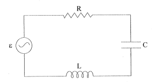
$\rightarrow$ As shown in the fig., a resistor, an inductor and a capacitor are connected in series in an $AC$ circuit.
$\rightarrow$ Voltage of the $AC$ source $v=v_m \sin \omega t$
$\rightarrow$ As the components are in series, ac current in each element is same, having the same amplitude and phase.
$\rightarrow$ Let current $i$ be :
$i=i_m \sin (\omega t+\phi)$
where, $\phi -$ is the phase difference between the voltage across the source and the current in the circuit.
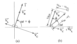
$\rightarrow$ In the fig. $(a),$ the phasor representing the current in the circuit as given by eq. $(1),$ is shown by $\vec{I}$.
$\rightarrow$ Further, $\vec{V}_L, \vec{V}_R, \vec{V}_C$ and $\vec{V}$ represent the voltage across inductor $L$, resistor $R$, capacitor C and the source, respectively.
$\rightarrow$ All the phasors are shown in the fig. with their corresponding phase difference.
$\rightarrow$ The length of these phasors or the amplitudes of $\overrightarrow{ V }_{ R }, \overrightarrow{ V }_{ C }$ and $\overrightarrow{ V }_{ L }$ are :
$\rightarrow$
$v_{ R m}=i_m R , v_{ C m}=i_m X _{ C }, v _{ L m}=i_m X _{ L }$
$\rightarrow$ From the phasor diagram, the equation of resultant voltage is as follows :
$\overrightarrow{ V }_{ L }+\overrightarrow{ V }_{ R }+\overrightarrow{ V }_{ C }=\overrightarrow{ V }$
(Note : voltage equation from the vertical components of above phasor relation can be written as : $v_L+v_R+v_C=v$ )
$\rightarrow$ Since $\vec{V}_C$ and $\vec{V}_L$ are always along the same line and in opposite directions, they can be combined into a single phasor $\left(\overrightarrow{ V }_{ C }+\overrightarrow{ V }_{ L }\right)$ which has a magnitude $\left|v_{ Cm }-v_{ Lm }\right|$.
$\rightarrow$ Since $\vec{V}$ is represented as the hypotenuse of a right$-$angle whose sides are $\vec{V}_R$ and $\vec{V}_C+\vec{V}_L$ the phythagorean theorem gives :
$\rightarrow v_m^2 =v_{ R m}^2+\left(v_{ C m}-v_{ L m}\right)^2$
$v_m^2 =\left(i_m R \right)^2+\left(i_m X _{ C }-i_m X _{ L }\right)^2$
$\therefore v_m^2 =i_m^2 R ^2+i_m^2\left( X _{ C }- X _{ L }\right)^2$
$\therefore v_m^2 =i_m^2\left[ R ^2+\left( X _{ C }- X _{ L }\right)^2\right]$
$\therefore i_m^2 =\frac{v_m^2}{ R ^2+\left( X _{ C }- X _{ L }\right)^2}$
$\therefore i_m =\frac{v_m}{\sqrt{ R ^2+\left( X _{ C }- X _{ L }\right)^2}}$
$\rightarrow$ The equation can also be written as follows :
$\therefore i_m=\frac{U_m}{Z}$
where, $Z=\sqrt{R^2+\left(X_C-X_L\right)^2}$
$\rightarrow Z$ is known as impedence of the given $AC$ circuit, which is analogous to resistance in a $DC$ circuit. Its unit is ohm $(\Omega) ($And it has the same dimension as resistance$).$
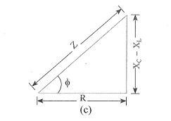
$\rightarrow$ Since phasor $\vec{I}$ is always parallel to phasor $\overrightarrow{V_R}$, the phase angle $\phi$ is the angle between $\overrightarrow{V_R}$ and $\overrightarrow{ V }$ and it is shown in fig. $(c).$
$\rightarrow \tan \phi=\frac{v_{ Cm }-v_{ Lm }}{v_{ Rn }}$
$\tan \phi=\frac{i_m X _{ C }-i_m X _{ L }}{i_{m R }}$
$\therefore \tan \phi=\frac{ X _{ C }- X _{ L }}{ R }$
$\rightarrow$ The diagram shown in fig. $(c)$ is known as Impedence diagram, which is a right-triangle with $Z$ as its hypotenuse.
View full question & answer→$\rightarrow$ As shown in the fig., a resistor, an inductor and a capacitor are connected in series in an $AC$ circuit.
$\rightarrow$ Voltage of the $AC$ source $v=v_m \sin \omega t$
$\rightarrow$ As the components are in series, ac current in each element is same, having the same amplitude and phase.
$\rightarrow$ Let current $i$ be :
$i=i_m \sin (\omega t+\phi)$
where, $\phi -$ is the phase difference between the voltage across the source and the current in the circuit.
$\rightarrow$ In the fig. $(a),$ the phasor representing the current in the circuit as given by eq. $(1),$ is shown by $\vec{I}$.
$\rightarrow$ Further, $\vec{V}_L, \vec{V}_R, \vec{V}_C$ and $\vec{V}$ represent the voltage across inductor $L$, resistor $R$, capacitor C and the source, respectively.
$\rightarrow$ All the phasors are shown in the fig. with their corresponding phase difference.
$\rightarrow$ The length of these phasors or the amplitudes of $\overrightarrow{ V }_{ R }, \overrightarrow{ V }_{ C }$ and $\overrightarrow{ V }_{ L }$ are :
$\rightarrow$
$v_{ R m}=i_m R , v_{ C m}=i_m X _{ C }, v _{ L m}=i_m X _{ L }$
$\rightarrow$ From the phasor diagram, the equation of resultant voltage is as follows :
$\overrightarrow{ V }_{ L }+\overrightarrow{ V }_{ R }+\overrightarrow{ V }_{ C }=\overrightarrow{ V }$
(Note : voltage equation from the vertical components of above phasor relation can be written as : $v_L+v_R+v_C=v$ )
$\rightarrow$ Since $\vec{V}_C$ and $\vec{V}_L$ are always along the same line and in opposite directions, they can be combined into a single phasor $\left(\overrightarrow{ V }_{ C }+\overrightarrow{ V }_{ L }\right)$ which has a magnitude $\left|v_{ Cm }-v_{ Lm }\right|$.
$\rightarrow$ Since $\vec{V}$ is represented as the hypotenuse of a right$-$angle whose sides are $\vec{V}_R$ and $\vec{V}_C+\vec{V}_L$ the phythagorean theorem gives :
$\rightarrow v_m^2 =v_{ R m}^2+\left(v_{ C m}-v_{ L m}\right)^2$
$v_m^2 =\left(i_m R \right)^2+\left(i_m X _{ C }-i_m X _{ L }\right)^2$
$\therefore v_m^2 =i_m^2 R ^2+i_m^2\left( X _{ C }- X _{ L }\right)^2$
$\therefore v_m^2 =i_m^2\left[ R ^2+\left( X _{ C }- X _{ L }\right)^2\right]$
$\therefore i_m^2 =\frac{v_m^2}{ R ^2+\left( X _{ C }- X _{ L }\right)^2}$
$\therefore i_m =\frac{v_m}{\sqrt{ R ^2+\left( X _{ C }- X _{ L }\right)^2}}$
$\rightarrow$ The equation can also be written as follows :
$\therefore i_m=\frac{U_m}{Z}$
where, $Z=\sqrt{R^2+\left(X_C-X_L\right)^2}$
$\rightarrow Z$ is known as impedence of the given $AC$ circuit, which is analogous to resistance in a $DC$ circuit. Its unit is ohm $(\Omega) ($And it has the same dimension as resistance$).$
$\rightarrow$ Since phasor $\vec{I}$ is always parallel to phasor $\overrightarrow{V_R}$, the phase angle $\phi$ is the angle between $\overrightarrow{V_R}$ and $\overrightarrow{ V }$ and it is shown in fig. $(c).$
$\rightarrow \tan \phi=\frac{v_{ Cm }-v_{ Lm }}{v_{ Rn }}$
$\tan \phi=\frac{i_m X _{ C }-i_m X _{ L }}{i_{m R }}$
$\therefore \tan \phi=\frac{ X _{ C }- X _{ L }}{ R }$
$\rightarrow$ The diagram shown in fig. $(c)$ is known as Impedence diagram, which is a right-triangle with $Z$ as its hypotenuse.