Question 13 Marks
What is Motional electromotive force $($emf$) ?$ Obtain motional emf $(\varepsilon)$= B I ${v}$ using proper example.
Answer
View full question & answer→$\rightarrow $"The induced emf arising due to some motion is called Motional emf."
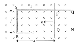
$\rightarrow $ As shown in figure, a rectangular conductor $\text{PQRS}$ is placed in a time independent, uniform magnetic field. If $\theta$ is the angle between $\vec{B}$ and area vector $\vec{A}$ of coil, then here $(\theta=0)$. Here, rod $PQ$ is free to do frictionless motion. Its effective length is $l$.
$\rightarrow $ On moving conductor $PQ$ with uniform velocity $\vec{v}$ as shown in figure, area enclosed by closed circuit $\text{PQRS}$ changes with time.
$\rightarrow $ Suppose, at any instant,
$RQ =x \ RS =l \text { then }$
Magnetic flux linked with closed loop $\text{PQRS}$ is
$\phi_{ B }= B I x(\because v=0 \rightarrow \cos \theta=1)$
$\rightarrow $ Distance $x$ changes with time, as a result, time rate of change of $\phi_{ B }$ induces emf.
$\therefore \varepsilon=-\frac{d \phi_{ B }}{d t}=-\frac{d}{d t} \text { (B } l x \text { ) [From eq. (1)] }$
$\therefore \varepsilon=- B l \frac{d x}{d t} \text { But } \frac{d x}{d t}=-0$
Where $v$ is speed of conductor $PQ$
$\therefore \varepsilon= B / v$
Equation $(2)$ is formula for motional emf.
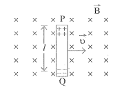
$\rightarrow $ As shown in figure, a conducting rod having length $l$ is moving with velocity $\vec{v}$ in direction perpendicular to uniform magnetic field $\vec{B}$.
$\rightarrow $ Lorentz force $F =q v B$ acts on free electric charges $($free electrons$)$ in rod $PQ.$
$\rightarrow $ Free electric charges experience this force towards $Q$ end of conductor. Thus, work done by Lorentz force to shift electric charge from $P$ to $Q$ is
$W = F l=q B{v}l$
$\rightarrow $ By definition of emf,
$e m f =\text { Work done on unit electric charge }$
$\therefore \varepsilon =\frac{ W }{q}$
$ =\frac{q B {v} l}{q}$
$\therefore \varepsilon = B{v}l$
This is expression for motional emf.
$\rightarrow $ As shown in figure, a rectangular conductor $\text{PQRS}$ is placed in a time independent, uniform magnetic field. If $\theta$ is the angle between $\vec{B}$ and area vector $\vec{A}$ of coil, then here $(\theta=0)$. Here, rod $PQ$ is free to do frictionless motion. Its effective length is $l$.
$\rightarrow $ On moving conductor $PQ$ with uniform velocity $\vec{v}$ as shown in figure, area enclosed by closed circuit $\text{PQRS}$ changes with time.
$\rightarrow $ Suppose, at any instant,
$RQ =x \ RS =l \text { then }$
Magnetic flux linked with closed loop $\text{PQRS}$ is
$\phi_{ B }= B I x(\because v=0 \rightarrow \cos \theta=1)$
$\rightarrow $ Distance $x$ changes with time, as a result, time rate of change of $\phi_{ B }$ induces emf.
$\therefore \varepsilon=-\frac{d \phi_{ B }}{d t}=-\frac{d}{d t} \text { (B } l x \text { ) [From eq. (1)] }$
$\therefore \varepsilon=- B l \frac{d x}{d t} \text { But } \frac{d x}{d t}=-0$
Where $v$ is speed of conductor $PQ$
$\therefore \varepsilon= B / v$
Equation $(2)$ is formula for motional emf.
$\rightarrow $ As shown in figure, a conducting rod having length $l$ is moving with velocity $\vec{v}$ in direction perpendicular to uniform magnetic field $\vec{B}$.
$\rightarrow $ Lorentz force $F =q v B$ acts on free electric charges $($free electrons$)$ in rod $PQ.$
$\rightarrow $ Free electric charges experience this force towards $Q$ end of conductor. Thus, work done by Lorentz force to shift electric charge from $P$ to $Q$ is
$W = F l=q B{v}l$
$\rightarrow $ By definition of emf,
$e m f =\text { Work done on unit electric charge }$
$\therefore \varepsilon =\frac{ W }{q}$
$ =\frac{q B {v} l}{q}$
$\therefore \varepsilon = B{v}l$
This is expression for motional emf.