Questions

5 Marks Questions

Take a timed test

6 questions · self-marked practice — reveal the answer and mark yourself.

Question 15 Marks
$i$. Draw a ray diagram showing the image formation by a compound microscope. Hence obtain the expression for total magnification when the image is formed at least distance of distinct vision.
$ii$. A compound microscope consists of an objective lens of focal length $2.0 \ cm$ and an eyepiece of focal length $6.0 \ cm$. If they are separated by a distance of $24 \ cm,$ find the total magnification when the image is formed at infinity.
Answer
Image

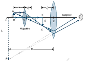
Magnification due to objective
$m_0=\frac{h^{\prime}}{h}=\frac{L}{f_0}\left(\because \tan \beta=\frac{h}{f_0}=\frac{h}{L}\right)$
Magnification due to eye piece when final image is formed at the near point
$m _{ e }=1+\frac{D}{f_{ e }}$
Total magnification
$ m = m _0 m_{ e }$
$m =\frac{L}{f_0}\left(1+\frac{D}{f_{ e }}\right)$
$ii. 4$
$m=\frac{L D}{f_o f_e}$
$m=\frac{24 \times 25}{2 \times 6}$
$=\frac{600}{12}$
$=50$
Hence, the total magnification when the image is formed at infinity is $50$.
View full question & answer
Question 25 Marks
Two point charges $-q$ and $q$ are located at points $(0, 0, - a)$ and $(0, 0, a)$ respectively.
$i$. Find the electrostatic potential at $(0, 0, z)$ and $(x, y, 0)$.
$ii$. How much work is done in moving a small test charge from the point $(5, 0, 0)$ to $(- 7, 0, 0)$ along the $x-$ axis?
$iii$. How would your answer change if the path of the test charge between the same points is not along the $x-$ axis but along any other random path?
$iv.$ If the above point charges are now placed in the same positions in the uniform external electric field $\vec{E}$, what would be the potential energy of the charging system in its orientation of unstable equilibrium?
Justify your answer in each case
Answer
We have, for a point charge, $V=\frac{1}{4 \pi \varepsilon_0} \cdot \frac{q}{r}$
$(i)$. At point $(0, 0, z)$ :
Potential due to the charge $(+q)$
$V_{+}=\frac{1}{4 \pi \varepsilon_0} \cdot \frac{q}{(z-a)}$
Potential due to the charge $(~q)$
$V_{-}=\frac{1}{4 \pi \varepsilon_0} \cdot \frac{(-q)}{(z+a)}$
Total Potential at $(0,0, z ) V = V _{+}+ V _{-}$
$=\frac{q}{4 \pi \varepsilon_0}\left[\frac{-1}{z+a}+\frac{1}{z-a}\right]$
$=\frac{2 q}{4 \pi \varepsilon_0\left(z^2-a^2\right)}$
At point $(x, y, 0)$
Potential due to the charge $+ q$
$V_{+}=\frac{1}{4 \pi \varepsilon_0} \cdot \frac{q}{\sqrt{x^2+y^2+a^2}}$
Potential due to the charge $(- q)$
$V_{-}=\frac{1}{4 \pi \varepsilon_0} \cdot \frac{-q}{\sqrt{x^2+y^2+a^2}}$
Total potential at $(x, y, 0)$
$=\frac{q}{4 \pi \varepsilon_0}\left(\frac{1}{\sqrt{x^2+y^2+a^2}}-\frac{1}{\sqrt{x^2+y^2+a^2}}\right)=0$
Hence total potential due to them at the given point will be zero.
$(ii)$. Work done $= q \left[ V _1- V _2\right]$
$V_1=0$ and $V_2=0$
$\therefore$ Work done $=0$
Where $V_1$ and $V_2$ are the total potential due to dipole at point $(5,0,0)$ and $(-7,0,0)$
$(iii)$. There would be no change
This is because the electrostatic field is a conservative field.
$($Alternatively: The work done, in moving a test charge between two given points is independent of the path taken ,it depends only on initial and final value.$)$
$(iv)$. The two given charges make an electric dipole of dipole moment $\vec{p}=q \cdot \overrightarrow{2 a}$
$P.E$. in the position of unstable equilibrium $\left(\theta=180^{\circ}\right. )\ ($where $\vec{p}$ and $\vec{E}$ are antiparallel to each other$) = pE \cos 180^{\circ}$
$\operatorname{Cos} 180^{\circ}=-1$
Thus potential energy is $=+ pE =2 aqE$
View full question & answer
Question 35 Marks
A series $\text{LCR}$ circuit is connected to an $a.c$. source having voltage $V=V_m \sin \omega t$. Derive the expression for the instantaneous current $I$ and its phase relationship to the applied voltage. Obtain the condition for resonance to occur. Define power factor. State the conditions under which it is
$i.$ maximum and
$ii$. minimum.
Answer
Suppose resistance $R$, inductance $L$ and capacitance $C$ are connected in series and an alternating source of voltage $V=V_0 \sin \omega t$ is applied across it. $($fig. $a)$ On account of being in series, the current $(i)$ flowing through all of them is the same.
Image
Suppose the voltage across resistance $R$ is $V _{ R }$, voltage across inductance $L$ is $V _{ L }$ and voltage across capacitance $C$ is $V _{ C }$. The voltage $V _{ R }$ and current $i$ are in the same phase, the voltage $V _{ L }$ will lead the current by angle $90^{\circ}$ while the voltage $V _{ C }$ will lag behind the current by angle $90^{\circ}$.
Clearly $V _{ C }$ and $V _{ L }$ are in opposite directions, therefore their resultant potential difference $= V _{ C }{ }^{-}$ $V_L\left(\right.$ if $\left.V_C>V L\right)$
Thus $V _{ R }$ and $\left( V _{ C }- V _{ L }\right)$ are mutually perpendicular and the phase difference between them is $90^{\circ}$.
As applied voltage across the circuit is $V,$ the resultant of $V _{ R }$ and $\left( V _{ C }- V _{ L }\right)$ will also be $V$ .
From fig.
$V ^2=V_R^2+\left(V_C-V_L\right)^2 $
$\Rightarrow V=\sqrt{V_R^2+\left(V_C-V_L\right)^2} \ldots \ldots . .( i )$
But $V_R=R i, V_C=X_C i$ and $V_L=X_L i \ldots. (ii)$
capacitance reactance and $X _{ L }=\omega L =$ inductive reactance
$\therefore V=\sqrt{(R i)^2+\left(X_C i-X_L i\right)^2}$
$\therefore$ Impedance of circuit, $Z=\frac{V}{i}=\sqrt{R^2+\left(X_C-X_L\right)^2}$
$Z=\sqrt{R^2+\left(X_C-X_L\right)^2}=\sqrt{R^2+\left(\frac{1}{\omega C}-\omega L\right)^2}$
Instantaneous current
$I=\frac{V_0 \sin (\omega t+\phi)}{\sqrt{R^2+\left(\frac{1}{\omega C}-\omega L\right)^2}}$
Condition for resonance to occur in series $\text{LCR}$ ac circuit:
For resonance, the current produced in the circuit and emf applied must always be in the same phase.
Phase difference $(\phi)$ in series $\text{LCR}$ circuit is given by
$\tan \phi=\frac{X_{C^{-}} X_L}{R}$
For resonance $\phi=0 $
$\Rightarrow X_C-X_L=0$
or $X_C=X_L$
If $\omega_r$ is resonant frequency, then
and $X_L=\omega_r L $
$ \therefore \frac{1}{\omega_r C}=\omega_r L $
$\Rightarrow \omega_r=\frac{1}{\sqrt{L C}}$
Power factor is the cosine of phase angle $\phi$, i.e., $\cos \phi= R / Z$.
For maximum power $\cos \phi=1$ or $Z = R$
i.e., circuit is purely resistive.
For minimum power $\cos \phi=0$ or $R =0$
i.e., circuit should be free from ohmic resistance.
View full question & answer
Question 45 Marks
$i$. Describe, with the help of a suitable diagram, the working principle of a step $-$ up transformer. Obtain the relation between input and output voltages in terms of the number of turns of primary and secondary windings and the currents in the input and output circuits.
$i$. Given the input current $15 A$ and the input voltage of $100 V$ for a step $-$ up transformer having $90\%$ efficiency, find the output power and the voltage in the secondary if the output current is $3 A$.
Answer
$i.$
Image
Working principle:
Step $-$ down transformer is made up of two or more coil wound on the iron core of the transformer.
It works on the principle of magnetic induction between the coils.
Whenever current in one coil changes an emf gets induced in the neighboring coil $($Principle of mutual induction$)$
Voltage across secondary
$V_s=e_s=-N_s \frac{d \phi}{d t}$
Voltage across primary
$ V _{ p }= e _{ p }=- N _{ p } \frac{d \phi}{d t}$
$\frac{V_s}{V_p}=\frac{N_s}{N_p}\left(\text { here, } N _{ s }> N _{ p }\right)$
In an ideal transformer
Power Input $-$ Power output
$ I _{ p } V _{ p }= I _{ S } V _{ S }$
$\therefore \frac{V_s}{V_p}=\frac{N_s}{N_p}=\frac{I_p}{I_s}$
$ii.$
Image
Input power, $P _{ i }= I _{ i } \times V _{ i }$
$=15 \times 100=1500 W$
Power output, $P _0= P _{ i } \times \frac{90}{100}=1350 W$
$\Rightarrow I _0 V=1350 W$
Output voltage $, V _0=\frac{1350}{3} V=450 V$
View full question & answer
Question 55 Marks
$a$ . Derive an expression for the potential energy of an electric dipole in a uniform electric field. Explain conditions for stable and unstable equilibrium.
$b$ . Is the electrostatic potential necessarily zero at a point where the electric field is zero? Give an example to support your answer.
Answer
Image
Since torque acting on dipole
$\vec{\tau}=\overrightarrow{ p } \times \overrightarrow{ E }$
$\vec{\tau}= pE \sin \theta \cdot \hat{ n }$
work done $d \omega=\tau \cdot d \theta$
$= pE \sin \theta d \theta$
$w =\int_{\theta_1}^{\theta_2} dw pE \int_{\theta_1}^{\theta_2} \sin \theta d \theta$
$ w = pE [-\cos \theta]_{\theta_1}^{\theta_2}$
$= pE \left[\cos \theta_1-\cos \theta_2\right]$
$\text { if } \theta_1=0, \theta_2=\theta$
$w = pE (1-\cos \theta)$
Conditions $-$
For stable equilibrium $-$ When electric dipole is parallel to electric field.
For unstable equilibrium $-$ Anti Parallel to electric field.
$b$. No.
Inside equipotential surface
View full question & answer
Question 65 Marks
Using Huygens' principle, draw a diagram to show propagation of a wavefront originating from a monochromatic point source. Explain briefly.
Answer
This principle is useful for determining the position of a given wavefront at any time in the future if we know its present position. The principle may be stated in three parts as follows:
i. Every point on a given wavefront may be regarded as a source of new disturbance.
ii. The new disturbances from each point spread out in all directions with the velocity of light and are called the secondary wavelets.
iii. The surface of tangency to the secondary wavelets in forward direction at any instant gives the new position of the wavefront at that time.
Let us illustrate this principle by the following example:
Let AB shown in the fig. be the section of a wavefront in a homogeneous isotropic medium at t = 0. We have to find the position of the wavefront at time t using Huygens' principle. Let v be the velocity of light in the given medium.
(a) Take the number of points 1, 2, 3, ... on the wavefront AB. These points are the sources of secondary wavelets.
(b) At time t the radius of these secondary wavelets is vt. Taking each point as centre, draw circles of radius vt.
(c) Draw a tangent $A_1 B_1$ common to all these circles in the forward direction. This gives the position of new wavefront at the required time $t$.
Image

The Huygens' construction gives a backward wavefront also shown by dotted line $A _2 B_2$ which is contrary to observation. The difficulty is removed by assuming that the intensity of the spherical wavelets is not uniform in all directions; but varies continuously from a maximum in the forward direction to a minimum of zero in the backward direction.
The directions which are normal to the wavefront are called rays, i.e., a ray is the direction in which the disturbance is propagated.

View full question & answer