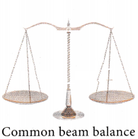
ommon (beam) balance :
A beam balance compares the sample mass with a standard reference mass (Standard reference masses are 5g, 10g, 20g, 50g, 100g, 200g, 500g, 1kg, 2kg, 5kg). This balance can measure mass accurately up to 5 g
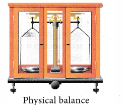
Physical balance:
This balance is used in labs and is similar to the beam balance but it is a lot more sensitive and can measure mass of an object correct to a milligram.
The standard, reference masses used in this physical balance are 10 mg, 20 mg, 50 mg, 100 mg, 200 mg, 500 mg, 1 g, 2g, 5 g, 10 g, 20 g, 50 g, 100g, and 200 g.

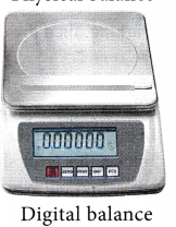
Digital balance:
Nowadays, for accurate measurements digital balances are used, which measure mass accurately even up to a few milligrams, the least value being 10 mg (Figure 1.11). This electrical device is easy to handle and commonly used in jewellery shops and labs.
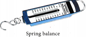
Spring balance:
This balance helps us to find the weight of an object. It consists of a spring fixed at one end and a hook attached to a rod at the other end. It works by ‘Hooke’s law’ which states that the addition of weight produces a proportional increase in the length of the spring. A pointer is attached to the rod which slides over a graduated scale on the right. The spring extends according to the weight attached to the hook and the pointer reads the weight of the object on the scale.