A carbon resistor has colour strips as violet, yellow brown and golden. The resistance is .............. $\Omega$
Medium


Download our appand get started for free
Experience the future of education. Simply download our apps or reach out to us for more information. Let's shape the future of learning together!No signup needed.*
Similar Questions
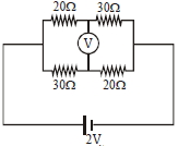
- 1The reading of an ideal voltmer in the circuit shown is.....$V$View Solution
- 2An unknown resistance $R_1$ is connected in series with a resistance of $10 \,\Omega$. This combinations is connected to one gap of a meter bridge while a resistance $R_2$ is connected in the other gap. The balance point is at $50\, cm$. Now, when the $10 \,\Omega$ resistance is removed the balance point shifts to $40\, cm$. The value of $R_1$ is (in $ohm$)View Solution
- 3A constant electric current $I$ is passed through a straight conductor of length $l$. If $S$ in specific charge of electron then the total momentum of electrons isView Solution
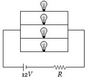
- 4Four identical electrical lamps are labelled $1.5\,V$, $0.5\,A$ which describes the condition necessary for them to operate at normal brightness. A $12\,V$ battery of negligible internal resistance is connected to lamps as shown, thenView Solution
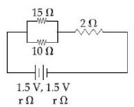
- 5In the given circuit, an ideal voltmeter connected across the $10\,\Omega $ resistance reads $2\, V$. The internal resistance $r$, of each cell is ................... $\Omega$View Solution
- 6A dry cell has an $e.m.f.$ of $1.5\, V$ and an internal resistance of $0.05\,\Omega $. The maximum current obtainable from this cell for a very short time interval is ................... $A$View Solution
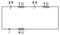
- 7For the circuit shown in the figure, the current $I$ will be .......$A$View Solution
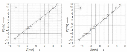
- 8Two students $P$ and $Q$ perform an experiment to verify Ohm's law for a conductor with resistance $R$. They use a current source and a voltmeter with least counts of $0.1 mA$ and $0.1 \,mV$, respectively. The plots of the variation of voltage drop $V$ across $R$ with current $I$ for both are shown below. The statement which is most likely to be correct?View Solution
- 9There are a large number of cells available, each marked $(6 \,V , 0.5 \,\Omega)$ to be used to supply current to a device of resistance $0.75 \,\Omega$, requiring $24 \,A$ current. How should the cells be arranged, so that power is transmitted to the load using minimum number of cells?View Solution
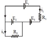
- 10The current $i_1$ and $i_2$ through the resistor $R_1 (= 10\,\Omega )$ and $R_2 (=30 \,\Omega )$ in the circuit diagram with $E_1 = 3\,V, E_2 = 3\,V$ and $E_3 = 2\,V$ are respectively:View Solution