A current of two amperes is flowing through a cell of $e.m.f.$ $5\, volts$ and internal resistance $0.5\, ohm$ from negative to positive electrode. If the potential of negative electrode is $10\,V$, the potential of positive electrode will be .............. $V$
Medium


Download our appand get started for free
Experience the future of education. Simply download our apps or reach out to us for more information. Let's shape the future of learning together!No signup needed.*
Similar Questions
- 1In a meter bridge experiment $\mathrm{S}$ is a standard resistance. $\mathrm{R}$ is a resistance wire. It is found that balancing length is $l=25 \;\mathrm{cm} .$ If $\mathrm{R}$ is replaced by a wire of half length and half diameter that of $\mathrm{R}$ of same material, then the balancing distance $\left.l^{\prime} \text { (in } \mathrm{cm}\right)$ will now beView Solution
- 2The terminal voltage across a battery of $\mathrm{emf}$ $E$ can beView Solution
- 3A wire has resistance $12\,\Omega $. It is bent in the form of a circle. The effective resistance between the two points on any diameter is equal to ................ $\Omega$View Solution
- 4$A$ simple circuit contains an ideal battery and a resistance $R$. If a second resistor is placed in parallel with the first,View Solution
- 5Two $220\; V , 100 \;W$ bulbs are connected first in series and then in parallel. Each time the combination is connected to a $220 \;V \;AC$ supply line. The power drawn by the combination in each case respectively will beView Solution
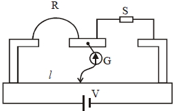
- 6An ammeter $A$ of finite resistance, and a resistor $R$ are joined in series to an ideal cell $C$. $A$ potentiometer $P$ is joined in parallel to $R$. The ammeter reading is $I_0$ and the potentiometer reading is $V_0$. $P$ is now replaced by a voltmeter of finite resistance. The ammeter reading now is $I$ and the voltmeter reading is $V$.View Solution

- 7View SolutionThe colour sequence in a carbon resistor is red, brown, orange and silver. The resistance of the resistor is
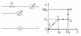
- 8In the circuit shown below (on the left) the resistance and the emf source are both variable. The graph of seven readings of the voltmeter and the ammeter ( $V$ and $I$, respectively) for different settings of resistance and the emf, taken at equal intervals of time $\Delta t$, are shown below (on the right) by the dots connected by the curve $E F G H$. Consider the internal resistance of the battery to be negligible and the voltmeter an ammeter to be ideal devices. (Take, $R_0 \equiv \frac{V_0}{I_0}$ ).View Solution
Then, the plot of the resistance as a function of time corresponding to the curve $E F G H$ is given by
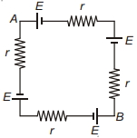
- 9Potential difference across $A B$ in the network shown is .........View Solution
- 10You are given three bulbs of $25$, $40$ and $60\, watt$. Which of them has lowest resistanceView Solution