Question
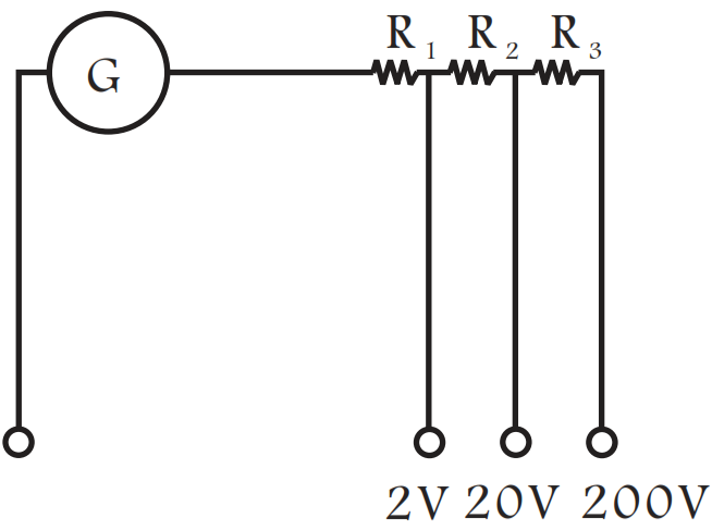
A multirange voltmeter can be constructed by using a galvanometer circuit as shown in Fig. We want to construct a voltmeter that can measure 2V, 20V and 200V using a galvanometer of resistance 10Ω and that produces maximum deflection for current of 1mA. Find R1, R2 and R3 that have to be used.

Answer

Key concept: The galvanometer can also be used as a voltmeter to measure the voltage across a given section of the circuit. For this a very high resistance wire is to be connected in series with galvanometer. The relationship is given by Ig(G + R) where Ig is the range of galvanometer, G is the resistance of galvanometer and R is the resistance of wire connected in series with galvanometer.

Applying expression in different situations

For Ig(G + R1) = 2 for 2V range

For Ig(G + R1 + R2) = 20 for 20V range

And For Ig(G + R1 + R2 + R3) = 200 for 200V range

By solving, we get

R1 = 1990Ω, R2 = 18kΩ and R3 = 180kΩ.

Need a full question paper?

Generate a complete, print-ready paper with questions like this in minutes — across 16+ boards, with answer keys.

Start Generating Free

Similar questions

a. State the condition for resonance to occur in series LCR a.c. circuit and derive an expression for resonant frequency.
b. Draw a plot showing the variation of the peak current $\left( i _{ m }\right)$ with frequency of the a.c, source used. Define the quality factor Q of the circuit.
Consider a metal ring kept (supported by a cardboard) on top of a fixed solenoid carrying a current I (see Fig). The centre of the ring coincides with the axis of the solenoid. If the current in the solenoid is switched off, what will happen to the ring?
Figure shows a square loop ABCD with edgelength a. The resistance of the wire ABC is r and that of ADC is 2r. Find the magnetic field B at the centre of the loop assuming uniform wires.

A 4.5 cm needle is placed 12 cm away from a convex mirror of focal length 15 cm. Give the location of the image and the magnification. Describe what happens as the needle is moved farther from the mirror.
An LR circuit with emf $\in$ is connected at t = 0.
  1. Find the charge Q which flows through the battery during 0 to t.
  2. Calculate the work done by the battery during this period.
  3. Find the heat developed during this period.
  4. Find the magnetic field energy stored in the circuit at time t.
  5. Verify that the results in the three parts above are consistent with energy conservation.
A narrow beam of singly-charged carbon ions, moving at a constant velocity of 6.0 × 10⁴m s-1, is sent perpendicularly in a rectangular region of uniform magnetic field B = 0.5T It is found that two beams emerge from the field in the backward direction, the separations from the incident beam being 3.0cm and 3.5cm. Identify the isotopes present in the ion beam. Take the mass of an ion = A(1.6 × 10⁻²⁷)kg, where A is the mass number.

Seven homogeneous bricks, each of length L, are arranged as shown in figure. Each brick is displaced with respect to the one in contact by $\frac{\text{L}}{10}.$ Find the x-coordinate of the centre of mass relative to the origin shown.

Consider the circuit shown in figure:
  1. Find the current through the battery a long time after the switch S is closed.
  2. Suppose the switch is again opened at t = 0. What is the time constant of the discharging circuit?
  3. Find the current through the inductor after one time constant.

Two particles A and B, each carrying a charge Q, are held fixed with a separation d between them. A particle C having mass m and charge q is kept at the middle point of the line AB.
  1. If it is displaced through a distance x perpendicular to AB, what would be the electric force experienced by it.
  2. Assuming x << d, show that this force is proportional to x.
  3. Under what conditions will the particle C execute simple harmonic motion if it is released after such a small displacement?
Find the time period of the oscillations if these conditions are satisfied.
Consider the circuit shown in the figure. Find (a) the current in the circuit (b) the potential drop across the $5\Omega$ resistor (c) the potential drop across the $10\Omega$ resistor. (d) Answer the parts (a), (b) and (c) with reference to the figure.