MCQ
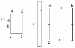
A rectangular loop of wire shown below is coplanar with a long wire carrying current $I$. The loop is pulled to the right a s indicated. What are the directions of the induced current in the loop and the magnetic forces on the left and the right sides of the loop?
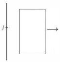
  Induced current Force on left side Force on right side
$a.$ Counter clockwise To the left To the right
$b.$ clockwise To the left To the right
$c.$ Counter clockwise To the right To the left
$d.$ clockwise To the right To the left

  • A
    $a.$
  • $b.$
  • C
    $c.$
  • D
    $d.$

Answer

Correct option: B.
$b.$
b
(b)

The loop $A B C D$ is moving from region of high flux to low flux in region of a downward magnetic field.

Following Lenz's law induced emf must be directed to increase the flux. Hence, direction of induced emf is clockwise in the loop.

Hence, current in wire and $A D$ length are parallel. So, there is attraction in wire and $A D$ length.

Similarly, there is repulsion in $B C$ and wire.

Need a full question paper?

Generate a complete, print-ready paper with questions like this in minutes — across 16+ boards, with answer keys.

Start Generating Free

Similar questions

Three voltmeters, all having different internal resistances are joined as shown in figure. When some potential difference is applied across $\mathrm{A}$ and $B$, their readings are $V_1, V_2$ and $V_3$. Choose the correct option.
A long straight wire of radius $a$ carries a steady current $I.$ The current is uniformly distributed over its cross-section. The ratio of  the magnetic fields $B$ and $B',$ at radial distances $\frac{a}{2}$ and $2a$ respectively, from the axis of the wire is 
Quantisation of charge was experimentally demonstrated by:
If the rheostat slider were to move from the extreme right to the far left, How will the reading of voltmeter $V_1$ change?
Which of the following wiring diagrams could be used to experimentally determine $R$ using ohm's law? Assume an ideal voltmeter and an ideal ammeter.
Which of the following statements concerning the depletion zone of an unbiased $ PN$  junction is (are) true

$(A)$ The width of the zone is independent of the densities of the dopants (impurities)
$(B)$ The width of the zone is dependent on the densities of the dopants
$(C)$ The electric field in the zone is produced by the ionized dopant atoms
$(D)$ The electric field in the zone is provided by the electrons in the conduction band and the holes in the valence band

In the following circuit, the resultant capacitance between $A$ and $B$ is $1\,\mu F$. Then value of $C$ is
In the following transistor amplifier circuit $\beta=50 . V_{C E}$ of the transistor is .......... $V$
An $\text{LCR}$ circuit has L = 10 mH, $\text{R}=3\Omega$ and $\text{C}=1\mu\text{ F}$ connected in series to a source of $15\cos\omega\text{t}$ volt. The current amplitude at a frequency that is $10\%$ lower than the resonant frequency is:
In the figure magnetic energy stored in the coil is