Question
✓
Answer
- (c) Power
Explanation:
In an ideal transformer, there is no power loss. The efficiency of an ideal transformer is $\eta=1$ (i.e 100%) i.e. input power = output power.
- (d) Obtain desired ac voltage and current.
Explanation:
Transformer is used to obtain desired ac voltage and current.
- (c) ac 110V
Explanation:
For a transformer, $\frac{\text{V}_\text{S}}{\text{V}_\text{p}}=\frac{\text{n}_\text{S}}{\text{n}_\text{p}}$
Where N denotes number of turns and V = voltage.
$\therefore{\text{V}_\text{S}}={\text{ac}\ 110}{\text{V}}$
- (a) Current through its secondary is about four times that of the current through its primary.
Explanation:
In a transformer the primary and secondary currents are related by,
$\text{I}_\text{S}=\Big(\frac{\text{N}_\text{S}}{\text{N}_\text{P}}\Big)\text{I}_\text{P}$
And the Voltage are related by,
$\text{V}_\text{S}=\Big(\frac{\text{N}_\text{P}}{\text{N}_\text{S}}\Big)\text{V}_\text{P}$
where subscripts p and s refer to the primary and secondary of the transformer.
Here, $\text{V}_\text{P}=\text{V},\frac{\text{N}_\text{P}}{\text{N}_\text{S}}=4\ \therefore\text{I}_\text{P}=4\text{I}_\text{P}$
and, $\text{V}_\text{S}=\Big(\frac{1}{4}\Big)\text{V}=\frac{\text{V}}{4}$
- (c) 90%
Explanation:
The efficiency of the transformer is:
$\eta=\frac{\text{output power}(\text{p}_\text{out})}{\text{intput power}(\text{p}_\text{in})}\times100$
Here, Pout = 100W, Pin = (220V)(0.5A) = 110W
$\therefore\eta=\frac{100\text{W}}{110\text{W}}\times100=90\%$
Need a full question paper?
Generate a complete, print-ready paper with questions like this in minutes — across 16+ boards, with answer keys.
Explore more
Similar questions
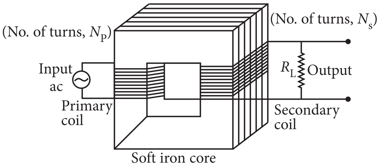
A transformer is essentially an a.c. device. It cannot work on d.c. It changes altemating voltages or currents. It does not affect the frequency of a.c. It is based on the phenomenon of mutual induction. A transformer essentially consists of two coils of insulated copper wire having different number of tums and wound on the same soft iron core.
The number of turns in the primary and secondary coils of an ideal transfonner are 2000 and 50 respectively. The primary coil is connected to a main supply of 120V and secondary coil is connected to a bulb of resistance $0.6\Omega.$
→The number of turns in the primary and secondary coils of an ideal transfonner are 2000 and 50 respectively. The primary coil is connected to a main supply of 120V and secondary coil is connected to a bulb of resistance $0.6\Omega.$
- The value of voltage across the secondary coil is:
- 5V
- 2V
- 3V
- 10V
- The value of current in the bulb is:
- 7A
- 15A
- 3A
- 5A
- The value of current in primary coil is:
- 0.125A
- 2.52A
- 1.51A
- 3.52A
- Power in primary coil is:
- 20W
- 5W
- 10W
- 15W
- Power in secondary coil is:
- 15W
- 20W
- 7W
- 8W
Consider a coin of Example 1.20. It is electrically neutral and contains equal amounts of positive and negative charge of magnitude 34.8kC. Suppose that these equal charges were concentrated in two point charges seperated by,
→- 1cm $\Big(\sim\frac{1}{2}\times\text{diagonalof theone paisa coin}\Big)$,
- 100m (~ length of a long building), and
- 106m (radius of the earth). Find the force on each such point charge in each of the three cases. What do you conclude from these results?
A galvanometer can be converted into voltmeter of given range by connecting a suitable resistance R, in series with the galvanometer, whose value is given by,
$\text{R}_\text{s}=\frac{\text{V}}{\text{I}_\text{g}}-\text{G}$
where Vis the voltage to be measured, lg is the current for full scale deflection of galvanometer and G is the resistance of galvanometer.
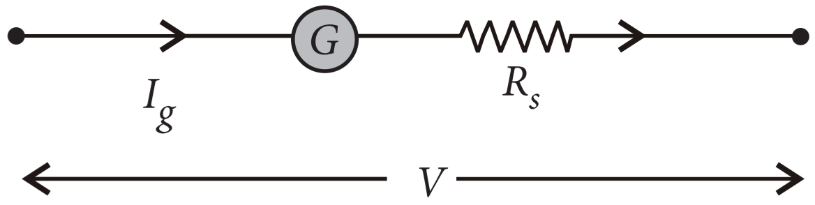
Series resistor(R,) increases range of voltmeter and the effective resistance of galvanometer. It also protects the galvanometer from damage due to large current. Voltmeter is a high resistance instrument and it is always connected in parallel with the circuit element across which potential difference is to be measured. An ideal voltmeter has infinite resistance. In order to increase the range of voltmeter n times the value of resistance to be connected in series with galvanometer is Rs = (n - 1)G.
→$\text{R}_\text{s}=\frac{\text{V}}{\text{I}_\text{g}}-\text{G}$
where Vis the voltage to be measured, lg is the current for full scale deflection of galvanometer and G is the resistance of galvanometer.
Series resistor(R,) increases range of voltmeter and the effective resistance of galvanometer. It also protects the galvanometer from damage due to large current. Voltmeter is a high resistance instrument and it is always connected in parallel with the circuit element across which potential difference is to be measured. An ideal voltmeter has infinite resistance. In order to increase the range of voltmeter n times the value of resistance to be connected in series with galvanometer is Rs = (n - 1)G.
- 10mA current can pass through a galvanometer of resistance $25\Omega$ What resistance in series should be connected through it, so that it is converted into a voltmeter of 100V?
- $0.975\Omega$
- $99.75\Omega$
- $975\Omega$
- $9975\Omega$
- There are 3 voltmeter A, B, C having the same range but their resistance are $15000\Omega,10000\Omega$, and $5000\Omega$ respectively. 'Tile best voltmeter amongst them is the one whose resistance is
- $5000\Omega$
- $10000\Omega$
- $15000\Omega$
- all are equally good.
- A milliammeter of range 0 to 25mA and resistance of $10\Omega$ is to be converted into a voltmeter with a range of 0 to 25V. 'Tile resistance that should be connected in series will be:
- $930\Omega$
- $960\Omega$
- $990\Omega$
- $1010\Omega$
- To convert a moving coil galvanometer (MCG) into a voltmeter:
- A high resistance R is connected in parallel with MCG.
- A low resistance R is connected in parallel with MCG.
- A low resistance R is connected in series with MCG.
- A high resistance R is connected in series with MCG.
- To increase the current sensitivity of a moving coil galvanometer, we should decrease:
- Zero.
- Low.
- High.
- Infinity.
A slide projector has to project a 35mm slide (35mm × 23mm) on a 2m × 2m screen at a distance of 10m from the lens. What should be the focal length of the lens in the projector?
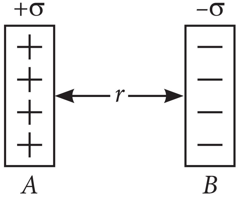
Surface charge density is defined as charge per unit surface area of surface charge distribution. i.e., $\sigma=\frac{\text{dq}}{\text{dS}}.$ Two large, thin metal plates are parallel and close to each other. On their inner faces, the plates have surface charge densities of opposite signs having magnitude of 17.0 × 10⁻²²Cm-2 as shown. The intensity of electric field at a point is $\text{E}=\frac{\sigma}{\in_0},$ where$\in_0=$ permittivity of free space.
→
- E in the outer region of the first plate is:
- 17 × 10-22 N/C
- 1.5 × 10⁻²⁵ N/C
- 1.9 × 10⁻¹⁰ N/C
- Zero.
- E in the outer region of the second plate is:
- 17 × 10-22 N/C
- 1.5 × 10⁻¹⁵ N/C
- 1.9 × 10⁻¹⁰ N/C
- Zero.
- E between the plates is:
- 17 × 10-22 N/C
- 1.5 × 10⁻¹⁵ N/C
- 1.9 × 10⁻¹⁰ N/C
- Zero.
- The ratio of E from right side of B at distances 2cm and 4cm, respectively is:
- 1 : 2
- 2 : 1
- 1 : 1
- $1:\sqrt{2}$
- ln order to estimate the electric field due to a thin finite plane metal plate, the Gaussian surface considered is:
- Spherical.
- Spherical.
- Straight line.
- None of these.
If the earth's magnetic field has a magnitude 3.4 × 10⁻⁵ T at the magnetic equator of the earth what would be its value at the earth's geomagnetic poles?
A deflection magnetometer is placed with its arms in north-south direction. How and where should a short magnet having $\frac{\text{M}}{\text{B}_\text{H}}=40\text{A-m}^2\text{T}$ be placed so that the needle can stay in any position?
→When white radiation is passed through a sample of hydrogen gas at room temperature, absorption lines are observed in Lyman series only. Explain.
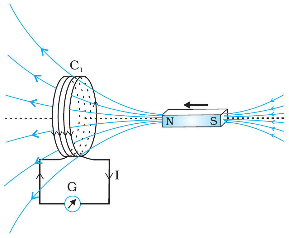
In year 1820 Oersted discovered the magnetic effect of current. Faraday gave the thought that reverse of this phenomenon is also possible i.e., current can also be produced by magnetic field. Faraday showed that when we move a magnet towards the coil which is connected by a sensitive galvanometer. The galvanometer gives instantaneous deflection showing that there is an electric current in the loop. Whenever relative motion between coil and magnet takes place an emf induced in coil. If coil is in closed circuit then current is also induced in the circuit. This phenomenon is called electromagnetic induction.
- The north pole of a long bar magnet was pushed slowly into a short solenoid connected to a galvanometer. The magnet was held stationary for a few seconds with the north pole in the middle of the solenoid and then withdrawn rapidly. The maximum deflection of the galvanometer was observed when the magnet was:
- Moving towards the solenoid.
- Moving into the solenoid.
- At rest inside the solenoid.
- Moving out of the solenoid.
- Two similar circular loops carry equal currents in the same direction. On moving the coils further apart, the electric current will.
- Remain unaltered.
- Increases in one and decreases in the second.
- Increase in both.
- Decrease in both.
- A closed iron ring is held horizontally and a bar magnet is dropped through the ring with its length along the axis of the ring. The acceleration of the falling magnet is.
- Equal to g.
- Less than g.
- More than g.
- Depends on the diameter of the ring and length of magnet.
- Whenever there is a relative motion between a coil and a magnet, the magnitude of induced emf set up in the coil does not depend upon the:
- Relative speed between the coil and magnet.
- Magnetic moment of the coil.
- Resistance of the coil.
- Number of turns in the coil.
- A coil of metal wire is kept stationary in a non-uniform magnetic field:
- A n emf and current both are induced in the coil.
- A current but no emf is induced in the coil.
- An emf but no current is induced in the coil.
- Neither emf nor current is induced in the coil.
For the past some time, Aarti had been observing some erratic body movement, unsteadiness and lack of coordination in the activities of her sister Radha, who also used to complain of severe headache occasionally. Aarti suggested to her parents to get a medical check-up of Radha. The doctor thoroughly examined Radha and diagnosed that she has a brain tumour.
- What, according to you, are the values displayed by Aarti?
- How can radioisotopes help a doctor to diagnose brain tumour?