Assertion : In a simple battery circuit, the point of the lowest potential is negative terminal of the battery.
Reason : The current flows towards the point of the higher potential, as it does in such a circuit from the negative to the positive terminal.
AIIMS 2010, Easy


Download our appand get started for free
Experience the future of education. Simply download our apps or reach out to us for more information. Let's shape the future of learning together!No signup needed.*
Similar Questions
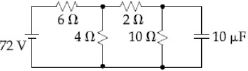
- 1Determine the charge on the capacitor in the following circuit ................ $\mu C$View Solution
- 2Two resistances of $400$ $\Omega$ and $800$ $\Omega$ are connected in series with $6\, volt$ battery of negligible internal resistance. A voltmeter of resistance $10,000$ $\Omega$ is used to measure the potential difference across $400$ $\Omega$. The error in the measurement of potential difference in volts approximately isView Solution
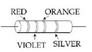
- 3View SolutionA resistance is shown in the figure. Its value and tolerance are given respectively by
- 4A wire $50\, cm$ long and $1\;mm^2$ in cross -section carries a current of $4\; A$ when connected to a $2\; V$ battery. The resistivity of the wire isView Solution
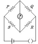
- 5In the Wheatstone's bridge shown, $P = 2\,\Omega ,$ $Q = 3\,\Omega ,$ $R = 6\,\Omega $ and $S = 8\,\Omega $. In order to obtain balance, shunt resistance across '$S$' must be .............. $\Omega$View Solution
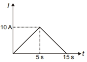
- 6Current $l$ versus time $t$ graph through a conductor is shown in the figure. Average current through the conductor in the interval $0$ to $15 \,s$ is ............ $A$View Solution
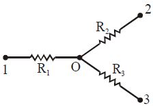
- 7.............. $A$ the current flowing through the resistance $R_2$ of the circuit shown in fig if the resistance are equal to $R_1 = 20\ \Omega, R_2 = 30 \ \Omega$ and $R_3 = 60 \ \Omega$ and potentials of points $1, 2$ and $3$ are equal to $V_1= 20\, V,$ $V_2 = 30\ V$ and $V_3 = 60\ V$View Solution
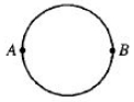
- 8A wire of resistance $12\,ohms$ per meter is bent to form a complete circle of radius $10\, cm.$ The resistance between its two diametrically opposite points, $A$ and $B$ as shown in the figure isView Solution
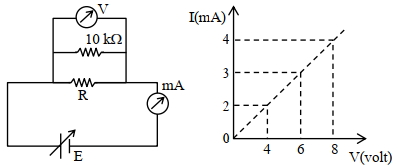
- 9To determine the resistance ($R$) of a wire, a circuit is designed below, The $V-I$ characteristic curve for this circuit is plotted for the voltmeter and the ammeter readings as shown in figure. The value of $\mathrm{R}$ is . . . . . . .$\Omega$View Solution
- 10An ideal battery of $4\, V$ and resistance $R$ are connected in series in the primary circuit of a potentiometer of length $1\, m$ and resistance $5\,\Omega $ . The value of $R$, to give a difference of $5\, mV$ across $10\, cm$ of potentiometer wire, is: ................ $\Omega$View Solution