MCQ
Below figures $(1)$ and $(2)$ represent lines of force. Which is correct statement
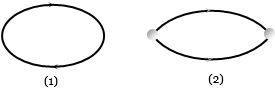
  • Figure $(1)$ represents magnetic lines of force
  • B
    Figure $(2)$ represents magnetic lines of force
  • C
    Figure $(1)$ represents electric lines of force
  • D
    Both figure $(1)$ and figure $(2)$ represent magnetic lines of force

Answer

Correct option: A.
Figure $(1)$ represents magnetic lines of force
a
(a) Magnetic lines of force always makes a closed loop.

Need a full question paper?

Generate a complete, print-ready paper with questions like this in minutes — across 16+ boards, with answer keys.

Start Generating Free

Similar questions

If the potential difference $V$ applied to the coolidge tube is doubled, then the cut off wavelength
At room temperature, a $P-$ type semiconductor has
Electron in hydrogen atom first jumps from third excited state to second excited state and then from second excited to the first excited state. The ratio of the  wavelengths $\lambda_1 :\lambda_2$ emitted in the two cases is
In photo-electric effect, when photons of energy ′hv′ are incident on a metal surface, electrons are emitted with some kinetic energy. It is possible to say that:
Five resistors are connected as shown in the diagram. The equivalent resistance between $A$ and $B$ is .............. $ohm$
The ratio of electric fields on the axis and at equator of an electric dipole will be
$A$ ray incident at an angle $53^o$ on a prism emerges at an angle at $37^o$ as shown. If the angle of incidence is made $50^o$, which of the following is a possible value of the angle of emergence......$^o$
Some electric bulbs are connected in series across a $220\, V$ supply in a room. If one bulb is fused then remaining bulbs are connected again in series across the same supply. The illumination in the room will
When some charge is transferred to $...A...$ it readily gets distributed over the entire surface of $... A...$ If some charge is put on $... B...$, it stays at the same place.
Here, $A$ and $B$ refer to.
To convert a 800 mV range milli voltmeter of resistance 40 W into a galvanometer of 100 mA range, the resistance to be connected as shunt is