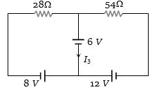
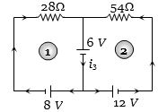
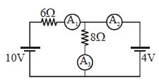
Consider the circuit shown in the figure. The current ${I_3}$ is equal to
Diffcult


Download our appand get started for free
Experience the future of education. Simply download our apps or reach out to us for more information. Let's shape the future of learning together!No signup needed.*
Similar Questions
- 1A cable of resistance $10\,\Omega $ carries electric power from a generator producing $250\, kW$ at $10000\, volt$, the power lost in the cable during transmission is ............. $kW$View Solution
- 2Two resistances ${R_1}$ and ${R_2}$ are made of different materials. The temperature coefficient of the material of ${R_1}$ is $\alpha $ and of the material of ${R_2}$ is $ - \beta $. The resistance of the series combination of ${R_1}$ and ${R_2}$ will not change with temperature, if ${R_1}/{R_2}$ equalsView Solution
- 3$12$ cells each having the same emf are connected in series and are kept in a closed box. Some of the cells are wrongly connected. This battery is connected in series with an ammeter and two cells identical with each other and also identical with the previous cells. The current is $3\, A$ when the external cells aid this battery and is $2\,A$ when the cells oppose the battery. How many cells in the battery are wrongly connected :-View Solution
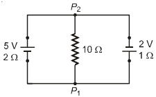
- 4A $5\ V$ battery with internal resistance $2\,\Omega$ and a $2\,V$ battery with internal resistance ln are connected to a $10\,\Omega$ resistor as shown in the figure.View Solution
- 5A certain wire has a resistance $R$. The resistance of another wire identical with the first except having twice its diameter isView Solution
- 6There are two wires of the same length and of the same material and radii $r$ and $2r$ . The ratio of their specific resistance isView Solution
- 7Dimensions of a block are $1\,cm \times 1\,cm \times 100\,cm$. If specific resistance of its material is $3 \times {10^{ - 7}}\,ohm - m$, then the resistance between the opposite rectangular faces isView Solution
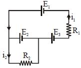
- 8The current $i_1$ and $i_2$ through the resistor $R_1 (= 10\,\Omega )$ and $R_2 (=30 \,\Omega )$ in the circuit diagram with $E_1 = 3\,V, E_2 = 3\,V$ and $E_3 = 2\,V$ are respectively:View Solution
- 9Reading of ammeter $A_1, A_2$ and $A_3$ will be respectivelyView Solution
- 10If six identical cells each having an $e.m.f.$ of $6\,V$ are connected in parallel, the $e.m.f.$ of the combination is ................ $V$View Solution