Rajasthan BoardEnglish MediumSTD 12 SciencePhysicsSEMICONDUCTOR ELECTRONICS: MATERIALS, DEVICES AND SIMPLE CIRCUITS4 Marks
Question
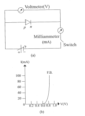
Explain the forward bias characteristics of $p-n$ junction diode with necessary graph.
✓
Answer
→The circuit arrangement for studying the V-I characteristics of a diode, (i.e. Variation of current I as a function of applied voltage V ) is shown in fig. (a). →As shown in Fig., the battery is connected to the diode through a potentiometer (or rheostat) so that the applied voltage to the diode can be changed. →For different values of voltages, the value of current is noted. A graph between V and I is obtained as shown in fig. (b). For the forward bias, the current is of the order of $m A$. →As it is seen in the fig., in forward bias, the current first increases very slowly, almost negligibly till the voltage across the diode crosses a certain value. →After the characteristic voltage, the diode current increases significantly (exponentially) even for a very small increase in the diode bias voltage. This voltage is called the threshold voltage or cut-in voltage ( $\sim 0.2 V$ for germanium diode and $\sim 0.7 V$ for silicon diode). →For diodes, the ratio of small change in voltage $\Delta V$ to a small change in current $\Delta I$ is called dynamic resistance. $r_d=\frac{\Delta V }{\Delta I }$ →Its unit is ohm $(\Omega)$. →The resistance of the diode in forward bias mode is approximately between $10 \Omega$ to $100 \Omega$.
Need a full question paper?
Generate a complete, print-ready paper with questions like this in minutes — across 16+ boards, with answer keys.