Question
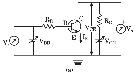
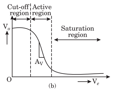
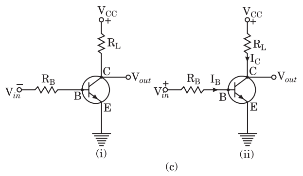
Explain the Function of a $n-p-n$ transistor as a switch with necessary circuit diagram.

Answer

Any device which can turn ON and OFF current in an electrical circuits in known as a switch. Generally, mechanical switches are used to resume and break connection in electrical circuits. Digital devices like computers perform a very large number of switching operations every day. In computer circuits an electronic device like junction diode and junction transistor can be used to turn rapidly on or off the current.
Junction Transistor as a Switch : In order to understood the switching action of a junction transistor we should be familiar with three states of working of a transistor. In Fig. (a), circuit diagram of an $n-p-n$ transistor in common-emitter configuration is shown. In this circuit a battery of variable voltage VBB IS connected to input circuit i.e., base-emitter circuit and another battery of variable voltage Vcc is connected to the output circuit i.e., emitter-collector circuit, RB and Re are the resistances in the input and output circuits, respectively.
Image
Now applying Kirchhoff's voltage rule in the closed loop of input side and output side, we get respectively as :
$V_{BB}=I_{B} R_{B}+V_{BE} \text { and } V_{CE}=V_{CC}-I_{C} R_{C}$ ... (1)
But the voltage $V_{B B}$ can be regarded as d.c. input voltage Vi and VCE as the d.c. output voltage VO Hence the above equation can be written as :
$V _i= I _{ B } R _{ B }+ V _{ BE }$ and $V _o= V _{ CC }- I _{ C } R _{ C }$ ...(2)
With the help of series (2) of the equation, a graph between $V _o$ and $V _i$ is drawn, which is called transfer characteristic of the junction transistor Fig. (b). This typical characteristic curve has three well defined regions as follows :
(i) Cut-off region : In Si transistor, as long as input Vi is less than 0.6 V the transistor remains in cut off state and current Ic remains zero.
$\therefore \quad V _o= V _{ CC }$
This region is called cut-off region.
(ii) Active region : When Vi becomes greater then 0.6 V tansistor is in active region with some current Ic in the output path and the output Vo decreases as the current $I _{ C }$ increases ( $V _o= V _{ CC }- I _{ C } R _{ C }$ ). With increase in $V _i, I _{ C }$ increases almost linearly and so $V _o$ decreases linearly till its value becomes less than about 1.0 V .
Image
(iii) Saturation Region : When Vi is further increased to a high value, the large collector current flows which produces such a large potential drop across the load Rc that the emitter-collector junction gets also forward biased. The output voltage Vo decreases to almost zero. Since it cannot pass any more collector currect IC, hence this situation is called saturation state and the transistor is said to be in saturation region.
A transistor can be used as a switch only if it is operated in its cut-off and saturation states. The electric circuit required to explain the switching action of a junction transistor is shown in Fig. (c) (i) in which common emitter $n-p-n$ transistor is used.
Image
When the base input voltage Vin is negative or zero as shown in Fig. (c) (ii), the transistor is cut-off (i.e., base current IB is zero) and no collector current flows in the load resistance RL connected to the collector circuit. As such, there is no voltage drop across RL. Hence the output voltage is equal to the collector supply voltage,
i.e. $V _{\text {out }}= V _{ CC }$
Strictly speaking, the collector current is not zero since a small collector-to-emitter leakage current always flows when the base input voltage is negative or zero.
When the base input voltage is positive [Fig. (c) (ii)], a base current IB flows and an amplified collector-current Ic flows through the load RL. Clearly, the output voltage is now given as follows :
$V _{\text {out }}= V _{ CC }- I _{ C } R _{ L }$
Thus, the transistor turns the current ON or OFF in the load RL depending upon whether the input base voltage is positive or negative (or zero). In other words, it acts like a switch.
An compared to other types of switches, the transistor switch is compact, noiseless, trouble-free and has a very fast speed of operation.

Need a full question paper?

Generate a complete, print-ready paper with questions like this in minutes — across 16+ boards, with answer keys.

Start Generating Free

Similar questions

An eye can distinguish between two points of an object if they are separated by more than 0.22mm when the object is placed at 25cm from the eye. The object is now seen by a compound microscope having a 20D objective and 10D eyepiece separated by a distance of 20cm. The final image is formed at 25cm from the eye. What is the minimum separation between two points of the object which can now be distinguished?
Figure shows two blocks A and B, each having a mass of 320g connected by a light string passing over a smooth light pulley. The horizontal surface on which the block A can slide is smooth. The block A is attached to a spring of spring constant 40N/m whose other end is fixed to a support 40cm above the horizontal surface. Initially, the spring is vertical and unstretched when the system is released to move. Find the velocity of the block A at the instant it breaks off the surface below it. Take g = 10m/s2.
A wave is described by the equation

$\text{y}=(1.0\text{mm})\sin\pi\Big(\frac{\text{x}}{2.0\text{cm}}-\frac{\text{t}}{0.01\text{s}}\Big).$

  1. Find the time period and the wavelength.
  2. Write the equation for the velocity of the particles. Find the speed of the particle at x = 1.0cm at time t = 0.01s.
  3. What are the speeds of the particles at x = 3.0cm, 5.0cm and 7.0cm at t 0.01s?
  4. What are the speeds of the particles at x 1.0cm at t = 0.011, 0.012, and 0.013s?
An electron falls through a distance of $1.5 cm$ in a uniform electric field of magnitude $2.0 \times 10^4 N C ^{-1}$ [Fig. 1.10(a)]. The direction of the field is reversed keeping its magnitude unchanged and a proton falls through the same distance [Fig. 1.10(b)]. Compute the time of fall in each case. Contrast the situation with that of 'free fall under gravity'.
Image
Find the value of $\frac{\text{i}_1}{\text{i}_2}$ in the figure. if (a) $\text{R}=0.1\Omega$ (b) $\text{R}=1\Omega$ and (c) $\text{R}=10\Omega.$ Note from your answers that in order to get more current from a combination of two batteries, they should be joined in parallel if the external resistance is small and in series if the external resistance is large, compared to the internal resistance.

Find the current measured by the ammeter in the circuit shown in the figure.

i. Prove that an ideal capacitor in an ac circuit does not dissipate power.
ii. An inductor of 200 mH, a capacitor of $400 \mu f$, and a resistor of $10 \Omega$ are connected in series to ac source of 50 V of variable frequency. Calculate the
a. the angular frequency at which maximum power dissipation occurs in the circuit and the corresponding value of the effective current and
b. value of Q-factor in the circuit.
Four point charges $q_{ A }=2 \mu C$,$q_{ B }=-5 \mu C , q_{ C }=2 \mu C$ and $q_{ D }=-5 \mu C$ are located at the of a square ABCD of side 10 cm. Wht is the force on a charge of $1 \mu C$ placed at the centre of the square?
Image
What is capacitance of a conductor? What is its unit? Find the formula for capacitance of an isolated spherical conductor. Draw a graph between capacitance and radius. If a spherical conductor is placed in dielectric constant $\in_r$, then what will be the effect on the value of capacitance?###If the area of each conducting plate of a parallel plate capacitor is A and the separation between them is $d$, then express the formula for its capacitance.
Let there be n resistors R1............Rn with Rmax = max (R1......... Rn) and Rmin = min {R1 ..... Rn}. Show that when they are connected in parallel, the resultant resistance RP < Rmin and when they are connected in series, the resultant resistance RS > Rmax. Interpret the result physically.