Gujarat BoardEnglish MediumSTD 12 SciencePhysicsSEMICONDUCTOR ELECTRONICS: MATERIALS, DEVICES AND SIMPLE CIRCUITS3 Marks
Question
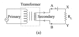
Explain with proper diagram, the application of a $p$ - $n$ junction diode as a halfwave rectifier.
✓
Answer
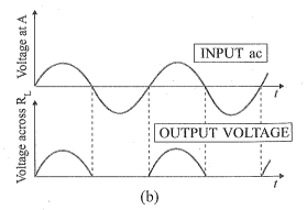
→The circuit diagram for the half-wave rectifier is shown in the figure. One $p-n$ junction diode is required in the half wave rectifier circuit. →As shown in fig. (a), the primary coil of a step down transformer is connected to an A.C. source. The secondary coil of transformer is connected in series with the $p-n$ junction diode and load resistance $R_L$. →The secondary of a transformer supplies the desired ac voltage across terminals A and B. When A is positive the diode is forward biased and it conducts. So, some output voltage is obtained between two terminals of load resistance $R_L$. →When A is negative, the diode is reverse-biased and it does not conduct. The reverse saturation current of a diode is negligible and can be considered equal to zero for practical purposes. →As shown in fig. (b), in the positive half cycle of ac there is a current through the load resistor $R _{ L }$ and we get an output voltage. Whereas there is no current in the negative half-cycle. In the next positive half cycle, again we get the output voltage. →Thus, the output voltage, though still varying, is restricted to only one direction and is said to be rectified. Since the rectified output of this circuit is only for half of the input ac wave so it is called the half-wave rectifier.
Need a full question paper?
Generate a complete, print-ready paper with questions like this in minutes — across 16+ boards, with answer keys.