MCQ
Figure shows a heavy block kept on a frictionless surface and being pulled by two ropes of equal mass $m$. At $t = 0,$ the force on the left rope is withdrawn but the force on the right end continues to act. Let $F_1$ and $F_2$ be the magnitudes of the forces by the right rope and the left rope on the block respectively:
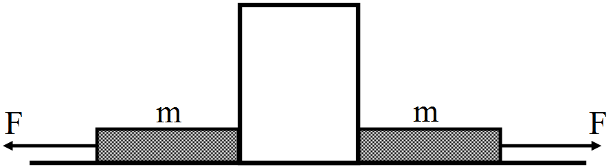
  • $F_1= F_2 = F$ for $t < 0.$
  • B
    $F_1 = F_2 = F + mg$ for $t < 0.$
  • C
    $F_1= F, F_2 = F$ for $t > 0.$
  • D
    $F_1< F, F_2 = F$ for $t > 0.$

Answer

Correct option: A.
$F_1= F_2 = F$ for $t < 0.$
At $t < 0,$ the block is in equilibrium in the horizontal direction.
So, $F_1= F_2 = F$
At $t > 0, F_2= 0$ and $F_1= F.$

Need a full question paper?

Generate a complete, print-ready paper with questions like this in minutes — across 16+ boards, with answer keys.

Start Generating Free

Similar questions

Obtain the equivalent capacitance of the network in Fig. For a 300V supply, determine the charge and voltage across each capacitor.
Figure shows a square loop of edge a made of a uniform wire. A current i enters the loop at the point A and leaves it at the point C. Find the magnetic field at the point P which is on the perpendicular bisector of AB at a distance $\frac{\text{a}}{4}$ from it.
Suppose the space between the two inner shells of the previous problem is filled with a dielectric of dielectric coastant K. Find the capacitance of the system between A and B.
A bar magnet of length 1cm and cross-sectional area $1.0cm^2$ produces a magnetic field of $1.5 \times 10.$ T at a point in end-on position at a distance 15cm away from the centre.
  1. Find the magnetic moment M of the magnet.
  2. Find the magnetization I of the magnet.
  3. Find the magnetic field B at the centre of the magnet.

Identify which logic gate OR, AND and NOT is represented by the circuits in the dotted line boxes 1, 2 and 3. Give the truth table for the entire circuit for all possible values of A and B.
Each capacitor in figure has a capacitance of $10\mu\text{F}.$ The emf of the battery is 100V. Find the energy stored in each of the four capacitors.
Find the current through the resistance R in figure. if.
  1. $\text{R}=12\Omega$
  2. $\text{R}=48\Omega$
Figure $4.13$ shows a long straight wire of a circular cross $-$ section $($radius $a)$ carrying steady current $I$. The current $I$ is uniformly distributed across this cross $-$ section. Calculate the magnetic field in the region $ra$.
Image
Describe the potential energy of an electric dipole in an external field in different positions also draw the diagram.
Define common potential. Find the expression for redistribution of charges and energy loss when capacitors are connected together.