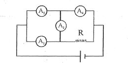
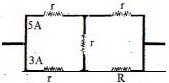
Four ammeters with identical internal resistance $r$ and a resistor $R$ are connected to a current source as given. if reading of $A_1$ and $A_2$ is $3\ A$ and $5\ A$ respectively then the reading $A_4$ is ............. $A$
Medium


Download our appand get started for free
Experience the future of education. Simply download our apps or reach out to us for more information. Let's shape the future of learning together!No signup needed.*
Similar Questions
- 1The equivalent resistance of a group of resistances is $R$. If another resistance is connected in parallel to the group , its new equivalent becomes $R_1$ and if it is connected in series to the group , its new equivalent becomes $R_2$ we have :View Solution
- 2In the box shown current $i$ enters at $H$ and leaves at $C$. If $i_{AB} = \frac{{\text{i}}}{6}$ , $i_{DC} = \frac{{\text{2i}}}{3}$ ,$i_{HA} = \frac{{\text{i}}}{2} , i_{GF} = \frac{{\text{i}}}{6} , i_{HE} = \frac{{\text{i}}}{6}$ , choose the branch in which current is zeroView Solution

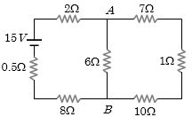
- 3The current from the battery in circuit diagram shown is .............. $A$View Solution
- 4A student is provided with a variable voltage source $V$, a test resistor $R_T=10\,\Omega$, two identical galvanometers $G_1$ and $G_2$ and two additional resistors, $R _1=10\,M\,\Omega$ and $R _2=0.001\,\Omega$. For conducting an experiment to verify ohms law, the most suitable circuit is:View Solution
- 5A current of $1\, mA$ is flowing through a copper wire. How many electrons will pass a given point in one secondView Solution
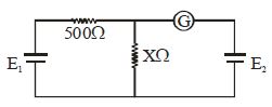
- 6In the adjoining circuit, the battery $E_1$ has an emf of $12\, volt$ and zero internal resistance while the battery $E_2$ has an $emf$ of $2\, volt$. If the galvanometer $G$ reads zero, then the value of the resistance $X$ (in $ohm$ ) isView Solution
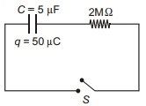
- 7The following circuit consist of a $5 \,\mu F$ capacitor, having charge $50 \,\mu C$ as shown. The switch is closed at $t=0$. The value of current in $2 \,M \Omega$ resistor at $t=0$ is ........... $\mu A$View Solution
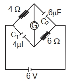
- 8A galvanometer $(G)$ $\Omega$ of 2 risistance is connected in the givn circuit the raito of charge in $C_1$ and $C_2$ is:View Solution
- 9We have a galvanometer of resistance $25\,\Omega $. It is shunted by a $2.5\,\Omega $ wire. The part of total current that flows through the galvanometer is given asView Solution
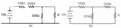
- 10A student was trying to construct the circuit shown in the figure below marked $(a)$, but ended up constructing the circuit marked $(b)$. Realising her mistake, she corrected the circuit, but to her surprise, the output voltage (across $R$ ) did not change. The value of resistance $R$ is ............ $\Omega$View Solution