If a wire is stretched to make it $0.1 \%$ longer, its resistance will
AIEEE 2011, Easy


Download our appand get started for free
Experience the future of education. Simply download our apps or reach out to us for more information. Let's shape the future of learning together!No signup needed.*
Similar Questions
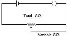
- 1View SolutionThe arrangement as shown in figure is called as
- 2Two wires of same material have length $L$ and $2L $ and cross-sectional areas $4A$ and $A$ respectively. The ratio of their specific resistance would beView Solution
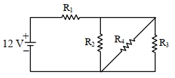
- 3In the given figure $R_1=10 \Omega, R_2=8 \Omega, R_3=4 \Omega$ and $R_4=8 \Omega$. Battery is ideal with emf $12 \mathrm{~V}$. Equivalent resistant of the circuit and current supplied by battery are respectively.View Solution
- 4The temperature dependence of resistances of $Cu$ and undoped $Si$ in the temperature range $300-400\ K$, is best described byView Solution
- 5A current of $2\, mA$ was passed through an unknown resistor which dissipated a power of $4.4\, W$. Dissipated power when an ideal power supply of $11\, V$ is connected across it isView Solution
- 6The equivalent resistance of a group of resistances is $R$. If another resistance is connected in parallel to the group , its new equivalent becomes $R_1$ and if it is connected in series to the group , its new equivalent becomes $R_2$ we have :View Solution
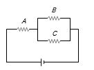
- 7Three identical resistances $A$, $B$ and $C$ are connected as shown in the given figure. The heat produced will be maximumView Solution
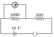
- 8In the given circuit, the voltmeter records $5\, volts$. The resistance of the voltmeter in $ohms$ isView Solution
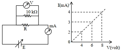
- 9To determine the resistance ($R$) of a wire, a circuit is designed below, The $V-I$ characteristic curve for this circuit is plotted for the voltmeter and the ammeter readings as shown in figure. The value of $\mathrm{R}$ is . . . . . . .$\Omega$View Solution
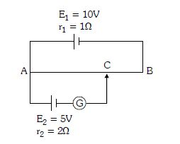
- 10In the figure the potentiometer wire of length $l =100\, cm$ and resistance $9\Omega$ is joined to a cell of emf $E_1 = 10V$ and internal resistance $r_1 = 1\Omega $. Another cell of emf $E_2 = 5\, V$ and internal resistance $r_2 = 2 \Omega $ is connected as shown. The galvanometer $G$ will show no deflection when the length $AC$ is ............... $cm$View Solution