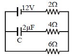
In the circuit here, the steady state voltage across capacitor $C$ is a fraction of the battery $e.m.f.$ The fraction is decided by
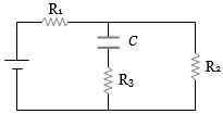
Medium


Download our appand get started for free
Experience the future of education. Simply download our apps or reach out to us for more information. Let's shape the future of learning together!No signup needed.*
Similar Questions
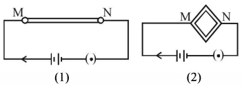
- 1A wire is connected to a battery between the point $M$ and $N$ as shown in the figure $(1)$. The same wire is bent in the form of a square and then connected to the battery between the points $M$ and $N$ as shown in the figure $(2)$. Which of the following quantities increases?View Solution
- 2Three resistances $P, Q, R$ each of $2 \,\,\Omega$ and an unknown resistance $S$ form the four arms of a Wheatstone bridge circuit. When a resistance of $6 \,\,\Omega$ is connected in parallel to $S$ the bridge gets balanced. What is the value of $S\,?$ ............... $\Omega$View Solution
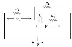
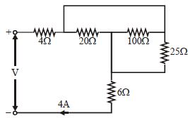
- 3In given circuit find value of ................... $V$View Solution
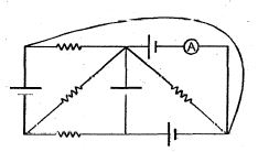
- 4In the circuit diagram shown, each battery is ideal having an e.m.f. of $1\ volt$. Each resistor has a resistance of $1\Omega $ Ammotor$(A)$ has a resistance of $1\Omega $ Find the reading of the ammeter and the total thermal power produced in the circuitView Solution
- 5An aluminium wire is stretched to make its length, $0.4 \,\%$ larger. Then percentage change in resistance is $.....\,\%$View Solution
- 6The charge flowing through a resistance $R$ varies with time according to $Q = at -bt^2.$ The total heat produced in $R$ is : (assume that direction of current not reversed)View Solution
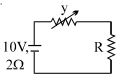
- 7In the figure shown the power generated in $y$ is maximum when $y = 5\,\Omega$ . Then $R$ is .............. $\Omega$View Solution
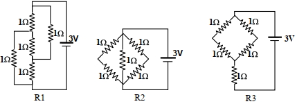
- 8Figure shows three resistor configurations $\mathrm{R} 1, \mathrm{R} 2$ and $\mathrm{R} 3$ connected to $3 \mathrm{~V}$ battery. If the power dissipated by the configuration $\mathrm{R} 1, \mathrm{R} 2$ and $\mathrm{R} 3$ is $\mathrm{P} 1, \mathrm{P} 2$ and $\mathrm{P} 3$, respectively, thenView Solution
Figure:
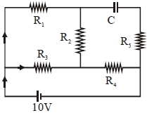
- 9Charge on the capacitor in the given circuit in steady state condition is :- ............... $\mu C$View Solution
- 10An ideal cell of emf $10\, V$ is connected in circuit shown in figure. Each resistance is $2\, \Omega .$ The potential difference (in $V$) across the capacitor when it is fully charged isView Solution