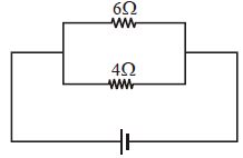
In the circuit shown, the power developed in the $6\,\Omega $ resistor is $6\,W.$ The power developed in the $4\,\Omega $ resistor is .............. $W$
Medium


Download our appand get started for free
Experience the future of education. Simply download our apps or reach out to us for more information. Let's shape the future of learning together!No signup needed.*
Similar Questions
- 1The resistance of a conductor is $5\, ohm$ at $50\,^oC$ and $6\, ohm$ at $100\,^oC$. Its resistance at $0\,^oC$ is ................ $ohm$View Solution
- 2Two batteries of different $e.m.f.'s$ and internal resistance connected in series with each other and with an external load resistor. The current is $3.0 \,A$. When the polarity of one battery is reversed, the current becomes $1.0 \,A$. The ratio of the $e.m.f.'s$ of the two batteries is ............View Solution
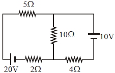
- 3In the figure shown, the current in the $10\, V$ battery is close toView Solution
- 4The current flowing through a lamp marked as $50\, W$ and $250\, V$ is ............. $amp$View Solution
- 5A storage battery has $e.m.f.$ $15\, volts$ and internal resistance $0.05\, ohm$. Its terminal voltage when it is delivering $10\, ampere$ is ............... $volts$View Solution
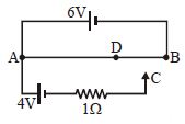
- 6A $6\, volt$ battery of negligible internal resistance resistance is connected across a uniform wire $AB$ of length $100\,cm$. The positive terminal of another battery of $emf$ $4\,V$ and internal resistance $1\,\Omega $ is joined to the point $A$ as shown in fig. Take the potential at $B$ to be zero. At which point $D$ of the wire $AB$, from left the potential is equal to the potential at $C$ ? ...................... $cm$ (approximately)View Solution
- 7A current of $5\; {A}$ is passing through a non-linear magnesium wire of cross-section $0.04\; {m}^{2}$. At every point the direction of current density is at an angle of $60^{\circ}$ with the unit vector of area of cross-section. The magnitude of electric field at every point of the conductor is ....${V} / {m}$ (Resistivity of magnesium is $\rho=44 \times 10^{-8}\, \Omega m$)View Solution
- 8$32$ cells, each of $emf$ $3V$, are connected in series and kept in a box. Externally, the combination shows an $emf$ of $84\, V$. The number of cells reversed in the combination isView Solution
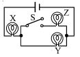
- 9If $X, Y$ and $Z$ in figure are identical lamps, which of the following changes to the brightnesses of the lamps occur when switch $S$ is closed?View Solution
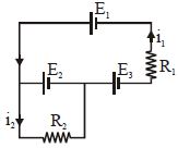
- 10The current $i_1$ and $i_2$ through the resistor $R_1 (= 10\,\Omega )$ and $R_2 (=30 \,\Omega )$ in the circuit diagram with $E_1 = 3\,V, E_2 = 3\,V$ and $E_3 = 2\,V$ are respectively:View Solution