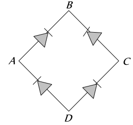
In the diagram, the input is across the terminals $A$ and $C$ and the output is across the terminals $B$ and $D$, then the output is


Download our appand get started for free
Experience the future of education. Simply download our apps or reach out to us for more information. Let's shape the future of learning together!No signup needed.*
Similar Questions
- 1Plate voltage of a triode is increased from $200 V$ to $225 V$. To maintain the plate current, change in grid voltage from $5 V$ to $5.75 V$ is needed. The amplification factor isView Solution
- 2View SolutionZener breakdown in a semi-conductor diode occurs when
- 3View SolutionDiode is used as a/an
- 4In the case of constants $\alpha$ and $\beta$ of a transistorView Solution
- 5A hole in a $P$-type semiconductor isView Solution
- 6In the $C B$ mode of a transistor, when the collector voltage is changed by $0.5$ volt. The collector current changes by $0.05\ mA$. The output resistance will beView Solution
- 7View SolutionIn a semiconductor
- 8View SolutionCorrect relation for triode is
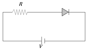
- 9For the given circuit of $P N$-junction diode, which of the following statement is correctView Solution
- 10A diode having potential difference $0.5 V$ across its junction which does not depend on current, is connected in series with resistance of $20 \Omega$ across source. If $0.1 A$ passes through resistance then what is the voltage of the sourceView Solution