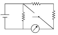
In the following circuit diagram, $E = 4\,V, r = 1\,\Omega$ and $R = 45\, \Omega$, then reading of the ammeter $A$ will be
Medium
Download our app for free and get started
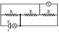
Using Nodal analysis
All resistances are in parallel
Equivalent circuit
$\mathrm{I}=\frac{\mathrm{V}}{\mathrm{R}_{\mathrm{eq}}}$
$\mathrm{I}=\frac{\mathrm{V}}{\frac{45}{3}+1}$
$=\frac{4}{16} \Rightarrow \frac{1}{4}$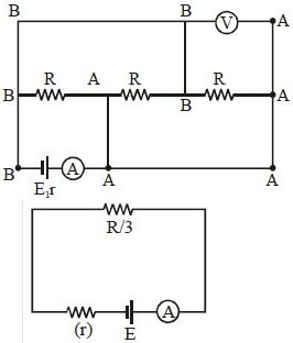

Download our appand get started for free
Experience the future of education. Simply download our apps or reach out to us for more information. Let's shape the future of learning together!No signup needed.*
Similar Questions
- 1A wire of length $L$ and $3$ identical cells of negligible internal resistances are connected in series. Due to current, the temperature of the wire is raised by $\Delta T$ in a time $t$. A number $N$ of similar cells is now connected in series with a wire of the same material and cross-section but of length $2\, L$. The temperature of the wire is raised by the same amount $\Delta T$ in the same time $t$. the value of $N$ isView Solution
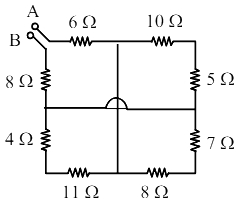
- 2The equivalent resistance between $A$ and $B$ is:View Solution
- 3A heater coil connected to a supply of a $220\, V$ is dissipating some power ${P_1}.$ The coil is cut into half and the two halves are connected in parallel. The heater now dissipates a power ${P_2}.$ The ratio of power ${P_1}\,\,:\,\,{P_2}$ isView Solution
- 4View SolutionThe electric current passing through a metallic wire produces heat because of
- 5For comparing the $e.m.f.$'s of two cells with a potentiometer, a standard cell is used to develop a potential gradient along the wires. Which of the following possibilities would make the experiment unsuccessfulView Solution
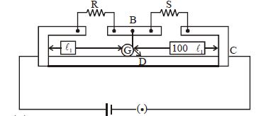
- 6In a meter bridge the point $D$ is neutral point as shown in the figure.View Solution
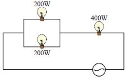
- 7Three electric bulbs of $200\,W,\,\,200\,W$ and $400\,W$ are shown in figure. The resultant power of the combination is ................ $W$View Solution
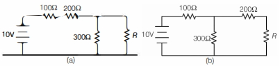
- 8A student was trying to construct the circuit shown in the figure below marked $(a)$, but ended up constructing the circuit marked $(b)$. Realising her mistake, she corrected the circuit, but to her surprise, the output voltage (across $R$ ) did not change. The value of resistance $R$ is ............ $\Omega$View Solution
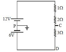
- 9Find potential at point $C$ and $D$View Solution
- 10In the circuit shown, the reading of the Ammeter is doubled after the switch is closed. Each resistor has a resistance $1\,\Omega $ and the ideal cell has an $e.m.f.$ $10\, V$. Then, the Ammeter has a coil resistance equal to ............... $\Omega$View Solution