It is preferable to measure the $e.m.f.$ of a cell by potentiometer than by a voltmeter because of the following possible reasons.
$(i)$ In case of potentiometer, no current flows through the cell.
$(ii)$ The length of the potentiometer allows greater precision.
$(iii)$ Measurement by the potentiometer is quicker.
$(iv)$ The sensitivity of the galvanometer, when using a potentiometer is not relevant.
Which of these reasons are correct?
AIEEE 2012, Diffcult


Download our appand get started for free
Experience the future of education. Simply download our apps or reach out to us for more information. Let's shape the future of learning together!No signup needed.*
Similar Questions
- 1A potentiometer is an accurate and versatile device to make electrical measurements of $EMF$ because the method involvesView Solution
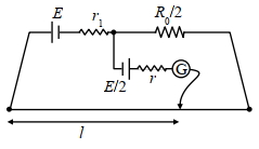
- 2In order to measure the internal resistance $r_1$ of a cell of emf $E$, a meter bridge of wire resistance $R_0=50 \Omega$, a resistance $R_0 / 2$, another cell of emf $E / 2$ (internal resistance $r$ ) and a galvanometer $G$ are used in a circuit, as shown in the figure. If the null point is found at $l=72 cm$, then the value of $r_1=$ . . . . $\Omega$View Solution
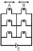
- 3Six similar bulbs are connected as shown in the figure with a $DC$ source of $emf\; E$, and zero internal resistance. The ratio of power consumption by the bulbs when $(i)$ all are glowing and $(ii)$ in the situation when two from section $A$ and one from section $B$ are glowing, will beView Solution
- 4A galvanometer together with an unknown resistance in series is connected to two identical batteries each of $1.5\, V$. When the batteries are connected in series, the galvanometer records a current of $1\,A$, and when batteries are in parallel the current is $0.6\,A$. What is the internal resistance of the battery ?View Solution
- 5Consider a metallic cube of edge length $L$. Its resistance, $R$, measured across its opposite faces is $R =\frac{ m _{ e } v }{ ne ^2 L ^2}$, where $n$ is the number density and $v$ is the drift speed of electrons in the cube, and $e$ and $m _{ e }$ are the charge and mass of an electron respectively. Assuming the de-Broglie wavelength of the electron to be $L$, the maximum resistance of the sample is closest to ............. $\,\Omega$ $\left(e=1.60 \times 10^{-19} \,C ; m _{ e }=9.11 \times 10^{-31} \,kg\right.$; Planck's constant, $h=6.63 \times 10^{-34} \,Js$ )View Solution
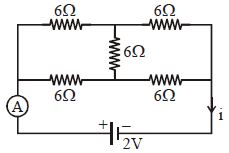
- 6View SolutionReading of ammeter in ampere for the following circuit is
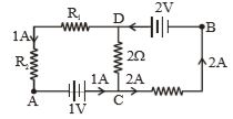
- 7In the circuit shown below, if the potential at point $A$ is taken to be zero, the potential at point $B$ is .............. $V$View Solution
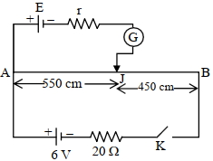
- 8In the given figure, there is a circuit of potentiometer of length $A B=10 \,{m}$. The resistance per unit length is $0.1 \,\Omega$ per ${cm}$. Across ${AB}$, a battery of emf ${E}$ and internal resistance ' ${r}^{\prime}$ is connected. The maximum value of emf measured by this potentiometer is : (In $V$)View Solution
- 9An expression for rate of heat generated, if a current of $I$ ampere flows through a resistance of $R$ $\Omega$, isView Solution
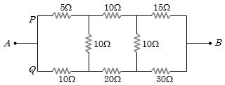
- 10In the arrangement of resistances shown below, the effective resistance between points $A$ and $B$ is ............... $\Omega$View Solution