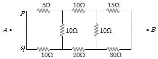
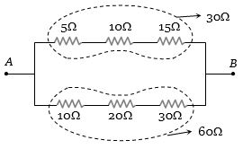
In the arrangement of resistances shown below, the effective resistance between points $A$ and $B$ is ............... $\Omega$
Medium


Download our appand get started for free
Experience the future of education. Simply download our apps or reach out to us for more information. Let's shape the future of learning together!No signup needed.*
Similar Questions
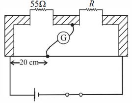
- 1Shown in the figure below is a meter-bridge set up with null deflection in the galvanometer. The value of the unknown resistor $R$ is ............. $\Omega$View Solution
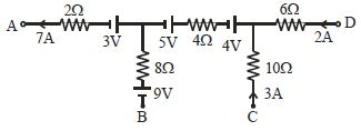
- 2In a portion of some large electrical network, curents in certain branches are known as shown in figure The value of $V_A -V_C$ is ............... $V$View Solution
- 3A letter $A$ is constructed of a uniform wire with resistance $1.0\,\Omega \,per\,cm$. The sides of the letter are $20\, cm$ and the cross piece in the middle is $10\, cm$ long. The apex angle is $60^o$. The resistance between the ends is .............. $\Omega$View Solution
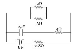
- 4In the figure shown, the capacity of the condenser $C$ is $2\,\mu F$. The current in $2\,\Omega $ resistor is ............... $A$View Solution
- 5Two wires that are made up of two different materials whose specific resistance are in the ratio $2 : 3$, length $3 : 4$ and area $4 : 5$. The ratio of their resistances isView Solution
- 6A wire of resitance $R$ and length $L$ is cut into $5$ equal part. if these parts are joined parts are joined paralley, than result resistance will be:View Solution
- 7In a potentiometer arrangement. $E_1$ is the cell establishing current in primary circuit. $E_2$ is the cell to be measured. $AB$ is the potentiometer wire and $G$ is a galvanometer. Which of the following are the essential condition for balance to be obtained.View Solution
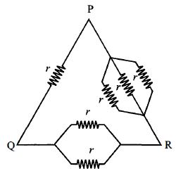
- 8Six equal resistances are connected between points $P, Q$ and $R$ as shown in figure. Then net resistance will be maximum betweenView Solution
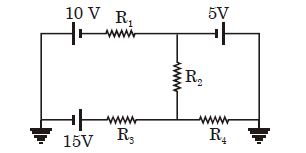
- 9In the circuit shown, current through $R_2$ is zero. If $R_4 = 2\,\Omega $ and $R_3 = 4\,\Omega $ , current through $R_3$ will be ................. $\mathrm{A}$View Solution
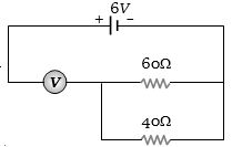
- 10The measurement of voltmeter in the following circuit is ................ $V$View Solution