Question
Locate the image formed by refraction in the situation shown in figure.

Answer


$\mu_1=1, \ \mu_2=1.5,$
R = 20cm (Radius of curvature), u = -25cm
$\therefore \ \frac{\mu_2}{\text{v}}-\frac{\mu_1}{\text{u}}=\frac{\mu_2-\mu_1}{\text{R}}$
$\Rightarrow\frac{1.5}{\text{v}}=\frac{0.5}{20}-\frac{1}{25}=\frac{1}{40}-\frac{1}{25}=\frac{-3}{200}$
$\Rightarrow \ \text{v}=200\times0.5=-100\text{cm}.$
So, the image is 100cm from (P) the surface on the side of S.

Need a full question paper?

Generate a complete, print-ready paper with questions like this in minutes — across 16+ boards, with answer keys.

Start Generating Free

Similar questions

An ideal battery sends a current of 5A in a resistor. When another resistor of value $10\Omega$ is connected in parallel, the current through the battery is increased to 6A. Find the resistance of the first resistor.
Three circuits, each consisting of a switch ‘S’ and two capacitors, are initially charged, as shown in the figure. After the switch has been closed, in which circuit will the charge on the left-hand capacitor (i) increase, (ii) decrease and (iii) remain same? Give reasons.
How much energy is released in the following reaction?
$\text{ }^7\text{Li + p}\rightarrow\alpha+\alpha.$
Atomic mass of $^7Li = 7.0160u$ and that of $^4He = 4.0026u.$
Show that the radiation pressure exerted by an EM wave of intensity I on a surface kept in vacuum is I/c.
Explain the construction of refracting telescope by figure and obtain the equation of magnification.
Draw a schematic diagram of the experimental arrangement used by Davisson and Germer to establish the wave nature of electrons. Explain briefly how the de-Broglie relation was experimentally verified in case of electrons.
Concentric equipotential surfaces due to a charged body placed at the centre are shown. Identify the polarity of the charge and draw the electric field lines due to it.
A circular coil of wire consisting of 100 turns, each of radius 8.0 cm carries a current of 0.40 A. What is the magnitude of the magnetic field B at the centre of the coil?
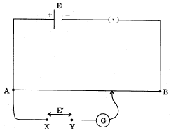
For the potentiometer circuit shown in the given figure, points X and Y reprensent the two terminals of an unknown emf E'. A student observed that when the jockey in moved from the end A to the end B of the potentiometer wire, the deflection in the galvanometer remains in the same direction.What may be the two possible faults in the circuit that could result in this obsevation?
If the galvanometer deflection at the end B is (i) more, (ii) less, than that at the end A, which of the two faults, listed above, would be there in the circuit?
Give reasons in support of your answer in each case.

A cylindrical bar magnet is kept along the axis of a circular coil and near it as shown in figure. Will there be any induced emf at the terminals of the coil, when the magnet is rotated:
  1. About its own axis.
  2. About an axis perpendicular to the length of the magnet?