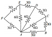
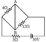
Six resistors of $3 \;\Omega$ each are connected along the sides of a hexagon and three resistors of $6\; \Omega$ each are connected along $A C, A D$ and $A E$ as shown in the figure. The equivalent resistance between $A$ and $B$ is equal to
AIPMT 1994, Medium


Download our appand get started for free
Experience the future of education. Simply download our apps or reach out to us for more information. Let's shape the future of learning together!No signup needed.*
Similar Questions
- 1An ammeter $A$ of finite resistance, and a resistor $R$ are joined in series to an ideal cell $C$. $A$ potentiometer $P$ is joined in parallel to $R$. The ammeter reading is $I_0$ and the potentiometer reading is $V_0$. $P$ is now replaced by a voltmeter of finite resistance. The ammeter reading now is $I$ and the voltmeter reading is $V$.View Solution

- 2A $25\, W$, $ 220\, V$ bulb and a $100\, W$, $220\, V$ bulb are connected in parallel across a $440\, V$ lineView Solution
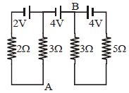
- 3Potential difference across $A B$ i.e., $V_A-V_B$ is ......... $V$View Solution
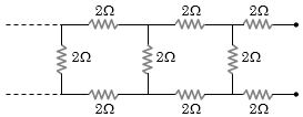
- 4View SolutionThe equivalent resistance of the following infinite network of resistances is
- 5$n$ identical cells are joined in series with its two cells $A$ and $B$ in the loop with reversed polarities. $EMF$ of each shell is $E$ and internal resistance $r$. Potential difference across cell $A$ or $B$ is (here $n > 4$)View Solution
- 6Two bulbs of $100\, W$ and $200\, W$ working at $220$ $volt$ are joined in series with $220$ $volt$ supply. Total power consumed will be approximately ........... $watt$View Solution
- 7View SolutionConsidering the following circuit, select the correct alternative
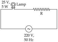
- 8A $220 \; V , 50 \; Hz$ AC source is connected to a $25 \; V$, $5 \; W$ lamp and an additional resistance $R$ in series (as shown in figure) to run the lamp at its peak brightness, then the value of $R$ (in ohm) will beView Solution
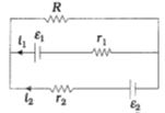
- 9View SolutionSee the electrical circuit shown in this figure. Which of the following equations is a correct equation for it ?
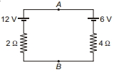
- 10In the given circuit calculate potential difference between $A$ and $B$ ............... $\mathrm{V}$View Solution