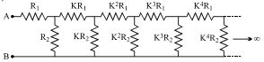
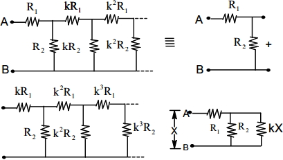
The circuit diagram shown consists of a large number of element (each element has two resistors $R_1$ and $R_2$). The resistance of the resistors in each subsequent element differs by $a$ factor of $K = 1/2$ from the resistance of the resistors in the previous elements. The equivalent reistance between $A$ and $B$ shown in figure is :
Advanced


Download our appand get started for free
Experience the future of education. Simply download our apps or reach out to us for more information. Let's shape the future of learning together!No signup needed.*
Similar Questions
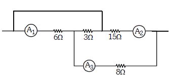
- 1A part of circuit is shown in figure. All the ammeters are ideal. If reading of ammeter $A_1$ is $1.0\ A$ , thenView Solution
- 2A potentiometer is an accurate and versatile device to make electrical measurements of $EMF$ because the method involvesView Solution
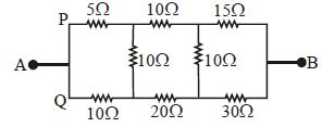
- 3In the arangement of resistances shown below, the effective resistance between points $A$ and $B$ is ............... $\Omega$View Solution
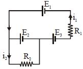
- 4The current $i_1$ and $i_2$ through the resistor $R_1 (= 10\,\Omega )$ and $R_2 (=30 \,\Omega )$ in the circuit diagram with $E_1 = 3\,V, E_2 = 3\,V$ and $E_3 = 2\,V$ are respectively:View Solution
- 5View SolutionThe equivalent resistance of resistors connected in series is always
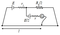
- 6In order to measure the internal resistance $r_1$ of a cell of emf $E$, a meter bridge of wire resistance $R_0=50 \Omega$, a resistance $R_0 / 2$, another cell of emf $E / 2$ (internal resistance $r$ ) and a galvanometer $G$ are used in a circuit, as shown in the figure. If the null point is found at $l=72 cm$, then the value of $r_1=$ . . . . $\Omega$View Solution
- 7A Copper $(Cu)$ rod of length $25\, {cm}$ and cross- sectional area $3\, {mm}^{2}$ is joined with a similar Aluminium $(Al)$ rod as shown in figure. Find the resistance of the combination between the ends $A$ and $B$ (in ${m} \Omega$)View Solution
(Take Resistivity of Copper $=1.7 \times 10^{-8}\, \Omega \,{m}$, Resistivity of Aluminium $=2.6 \times 10^{-8}\, \Omega \,{m}$ )

- 8View SolutionConsider four circuits shown in the figure below. In which circuit power dissipated is greatest (Neglect the internal resistance of the power supply)
- 9In a potentiometer experiment the balancing with a cell is at length $240\,cm$ . On shunting the cell with a resistance of $2\,\Omega $ , the balancing length becomes $120\, cm$ . The internal resistance of the cell is ................... $\Omega$View Solution
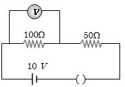
- 10In the given circuit, the voltmeter records $5\, volts$. The resistance of the voltmeter in $ohms$ isView Solution