Alternating Current — Physics STD 12 Science — Question
Rajasthan BoardEnglish MediumSTD 12 SciencePhysicsAlternating Current5 Marks
Question
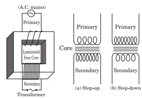
What is transformer ? Describe its construction and working principle.
✓
Answer
Transformer : Transformer is a device by which an alternating voltage may be decreased or increased. This is based on the principle of mutual induction. Construction : It consists of laminated core of soft iron, on which two coils of insulated copper wire are separately wound. These coils are kept insulated from each other and frm the iron-core, but are coupled through mutual induction. The number of turns in these coils are different. Out of these coils one coil is called primary coil and other is called the secondary coil. The terminals of primary coils are connected to AC mains and the terminals of the secondary coil are connected to external circuit in which alternating current of desired voltage is required. Transformers are of two types : 1. Step-up Transformer : It transforms the alternating low voltage to alternating high voltage and in this the number of turns in secondary coil is more than that in primary coil. (i.e., $N _s > N _p$ ). 2. Step-down Transformer : It transforms the alternating high voltage to alternating low voltage and in this the number of turns in secondary coil is less than that in primary coil (i.e., $N _s < N _p$ ). Working Principle : When alternating current source is connected to the ends of primary coil, the current changes continuously in the primary coil; due to which the magnetic flux linked with the secondary coil changes continuously, therefore the alternating emf of same frequency is developed across the secondary. Let Np be the number of turns in primary coil, Ns the number of turns in secondary coil and I the magnetic flux linked with each turn. We assume that there is no - leakage of flux so that the flux linked with each turn of primary coil and secondary coil is the same. According to Faraday's laws the emf induced in the primary coil. $e_p=- N _p\left(\frac{\Delta \Phi}{\Delta t}\right)$ and emf induced in the secondary coil $e_s=- N _s\left(\frac{\Delta \Phi}{\Delta t}\right)$ $\therefore \quad \frac{e_s}{e_p}=\frac{- N _s\left(\frac{\Delta \Phi}{\Delta t}\right)}{- N _p\left(\frac{\Delta \Phi}{\Delta t}\right)} \Rightarrow \frac{e_s}{e_p}=\frac{ N _s}{N_p}$ ...(1) If the resistance of the primary circuit is negligible then there will be no energy loss. Hence the induced emf ep in primary will be numerically equal to the applied voltage Vp across the primary. Further, if the secondary circuit is open then the voltage Vs across the terminals of the secondary coil will be equal to the induced emf es. Under these ideal conditions, we have $\frac{e_s}{e_p}=\frac{ V _s}{V_p}$ ...(2) Thus from equations (1) and (2), we get $\frac{ V _s}{V_p}=\frac{ N _s}{N_p}$ ...(3) The ratio Ns/Np = r is called the transformation ratio of the transformer. For step-up transformer Ns > Np and for step-down transformer Ns < Np hence the value of r is greater than 1 for step-up transformer and less than 1 for step-down transformer. Hence from equation (3), we have Vs/Vp = r ⇒ Vs = r. Vp. Therefore in step-up transformer Vs > Vp and in step-down transformer Vs < Vp. If $I_p$ and $I_s$ be the currents at any instant in primary and secondary coil and power loss be negligible, then in ideal condition : Power in secondary = Power in primary i.e., $V _s \times I _s= V _p \times I _p$ $\Rightarrow \quad \frac{ I _p}{ I _s}=\frac{ V _s}{V_s}$ ...(4) $\Rightarrow \quad \frac{ I _p}{ I _s}=\frac{ N _s}{N_p}$ ...(5) $\begin{array}{ll}\therefore & \frac{ I _p}{ I _s}=\frac{ V _s}{V_s}=\frac{ N _s}{N_p}=r\end{array}$ ...(6) $\frac{ I _p}{ I _s}=r$ $\Rightarrow I _p=r . I _s$ and as r is greater than 1 for step-up transformer and less than 1 for step-down transformer, hence Is < Ip, in step-up transformer and Is > Ip in step down transformer. Thus when the voltage is stepped up i.e. increased the current is correspondingly stepped down i.e.reduced in the same ratio and vice-versa under ideal conditions. But in practice it is not possible because the output power is always less than input power due to many energy losses in the transformer.
Need a full question paper?
Generate a complete, print-ready paper with questions like this in minutes — across 16+ boards, with answer keys.