Question 12 Marks
Derive the equation of instantaneous power and average power for a purely capacitive? circuit.
Answer
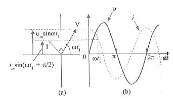
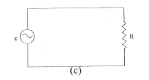
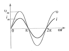
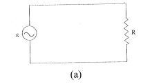
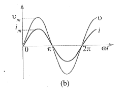
View full question & answer→→Voltage of AC source $v=v_m \sin \omega t$
→Current in a circuit containing only capacitors is
$i=i_m \sin \left(\omega t+\frac{\pi}{2}\right)$
→Where,
$i_m=\frac{v_m}{ X _{ C }}=\frac{v_m}{\frac{1}{\omega C }}$ Amplitude of electric current
→The instantaneous power supplied to the capacitor is,
$\begin{aligned}
p & =v i \\
\therefore p & =v_m i_m \sin \omega t \sin \left(\omega t+\frac{\pi}{2}\right) \\
\therefore p & =v_m i_m \sin \omega t \cos \omega t \\
\therefore \quad p & =\frac{v_m i_m}{2}(2 \sin \omega t \cos \omega t)
\end{aligned}$
But, $2 \sin \omega t \cos \omega t=\sin 2 \omega t$
$\therefore p=\frac{v_m i_m}{2} \sin 2 \omega t$
→Average power (during one complete cycle)
$\begin{array}{l}
P =\bar{p}=\left\langle\frac{v_m i_m}{2} \sin 2 \omega t\right\rangle \\
\therefore P =\frac{v_m i_m}{2}<\sin 2 \omega t> \\
\text { But },<\sin 2 \omega t>=0 \\
\therefore P =0
\end{array}$
→Thus, average power supplied to a capacitor during one complete cycle is zero.
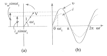