Question 13 Marks
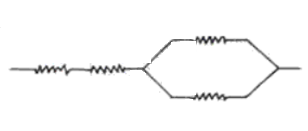
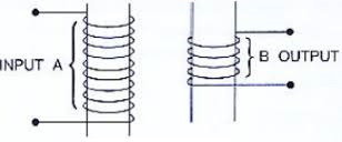
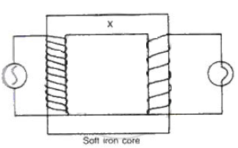
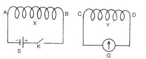
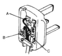
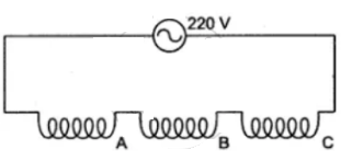
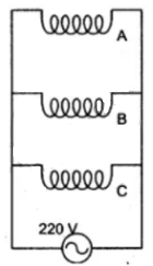
Complete the following diagram of a transformer and name the parts labeled A and B. Name the part you have drawn to complete the diagram . What is the material of this part? In this transformer a step-up or step-down? Why?
Answer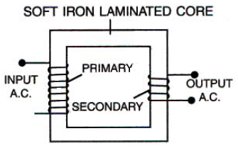
View full question & answer→ The part drawn to complete the diagram is the core.
Material of core is soft-iron .
It is a step down transformer because the number of turns in the primary is more than the number of turns in the secondary.
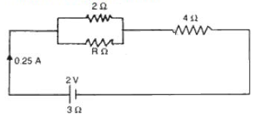
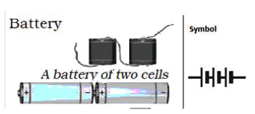
 When two or mo re cells are connected together such that the positive terminaI of one cell is connected to the negative terminal of the next cell; such a combination of two or more cells is called a battery. A battery is thus a combination of two or more cells.