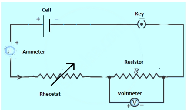
Questions

[5 Mark Question Answer]

🎯

Test yourself on this topic

19 questions · timed · auto-graded

Question 15 Marks
A cell supplies a current of 1.2 A through two $2 \Omega$ resistors connected in parallel. When the resistors are connected in series, if supplies a current of $0.4 A$ . Calculate the internal resistance and e.m.f of the cell.
Answer
Let e be the emf of the cell and $r$ be its internal resistance.
Case I: In parallel,
total resistance, $R p=(r+1) \Omega$
total current $=1.2 A$
$\therefore e=1.2(r+1)...........(1)$
Case II : In series,
total resistance, $R _{ S }=( r +4) \Omega$
total current $=0.4 A$
$\therefore e=0.4(r+4)..........(2)$
From (i) and (ii)
$1.2(r+1)=0.4(r+4)$
or, $3(r+1)=(r+4)$
or, $3 r+3=r+4$
or, $r=0.5 \Omega$
Putting this value of $r$ in (ii) we get:
$e=0.4(0.5+4)$
or, $e=1.8 V$
$\therefore r=0.5 o \text { and } e=1.8 V$
View full question & answer
Question 25 Marks
Fig. shows a simple form of an A.C. generator.

Image

(a) Name the parts labeled A and B.
(b) What would be the effect of doubling the number of turns on the coil if the speed of rotation remains unchanged?
(c) Which of the output terminals is positive if the coil is rotating in the
direction shown in the diagram (anticlockwise)?
( d ) What is the position of the rotating coil when p.d. across its ends is zero? Explain why p.d. is zero when the coil is at this position .
(e) Sketch a graph showing how the p.d. across the ends of the rotating coil varies with time for an A.C. dynamo.
( f) On th e same sheet of paper and vertically below the first graph using the same time scale, sketch graphs to show the effect of
(i) Doubling the speed of rotation and at the same time keeping
the field and the number of turns constant,
(ii ) Doubling the number of turns on the coil and at the same time
doubling the speed of rotation of the coil, keeping th e speed
constant.

Answer
Image (b) Increasing the number of turns will increase th e current through the coil .
(c) Terminal X will be posi tive.
( d ) When the plane of the coil is normal to the magnetic field, the magnetic flux linked with the coil is maximum and the p.d. across its ends is zero.
Image
View full question & answer
Question 35 Marks
Fig . shows the core of a transformer and i ts input and output connections

Image

State the material used for the core and describe th e structure of the core.
(a) Use the values given in the diagram to calculate the turns ratio for the transformer and connections, labeling all parts of the diagram .
(b) If a current of 2 A is taken from th e output, calculate th e current in the input circuit (Assume the transformer to be ideal ).

Answer
(a) Soft iron is used as the material for the core of transformer.
Structure of core: The core is made by taking thin rectangular sheets or laminas of soft iron (or silicon -steel) and dipping them in an insulating paint or varnish . These insulated sheets are stacked together to form a solid looking rectangular frame. This is called the laminated core of the transformer.
(b) Given,$E_p=250 \mathrm{~V}, \mathrm{E} .=50 \mathrm{~V}$
We know that for transformer turn ratio =$\frac{N_s}{N_p}=\frac{E_s}{E_p}$
$\frac{\mathrm{N}_{\mathrm{s}}}{\mathrm{N}_{\mathrm{P}}}=\frac{50}{250}=\frac{1}{5}$
Thus, it is a step-down transformer.
Image
Given,$\mathrm{I}_{\mathrm{S}}=2 \mathrm{~A}$
Let $I_p$be the current though primary.
We know that for transformer turn ratio =$\frac{I_p}{I_s}=\frac{E_5}{E_s}=\frac{1}{5}$
$\mathrm{I}_{\mathrm{p}}=\frac{1}{5} \times 2=0.4 \mathrm{~A}$
View full question & answer
Question 45 Marks
Describe two experiments to illustrate the production of electric current by electromagnetic induction. State the laws which determine the direction and magnitude of the induced current.
Answer
Experiment 1
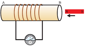
(i) Take a coil of wire AB having a large number of turns.
(ii ) Connect the ends of the coil to a galvanometer as shown in figure.
(iii ) Take a strong bar magnet and move i ts north pole towards the end B of the coil.
(iv) There is a momentary deflection in the needle of the galvanometer, say to the right. This indicates the presence of a current in the coil AB. The deflection becomes zero the moment the motion of the magnet stops.
(v) Now withdraw the north pole of the magnet away from the coil. Now the galvanometer is deflected toward the left, showing that th e current is now set up in the direction opposi te to the first.
(vi) Place the magnet stationary at a point near to the coil, keeping i ts north pole towards the end B of the coil. We see that the galvanometer needle deflects toward the right when the coil is moved towards the north pole of the magnet. Similarly the needle moves toward left when the coil is moved away.
(v) When the coil is kept stationary with respect to the magnet, the deflection of the galvanometer drops to zero.

Image Experiment 2
(i) Take two different coils of copper wire having large number of turns (say 50 and 100 turns respectively). Insert them over a non -conducting cylindrical roll, as shown in figure.
(ii ) Connect the coil -1, having larger number of turns, in series with a battery and a plug key. Also connect th e other coil -2 with a galvanometer as shown .
(iii ) Plug in the key. Observe the galvanometer. We will observe that the needle of the galvanometer instantly jumps to one side and just as quickly returns to zero, indicating a momentary current in coil -2.
(iv) Disconnect coil -1 from the battery. We will observe that the needle
momentarily moves, but to the opposi te side. It means that now the current flows in the opposi te direction in coil -2.
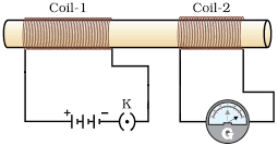
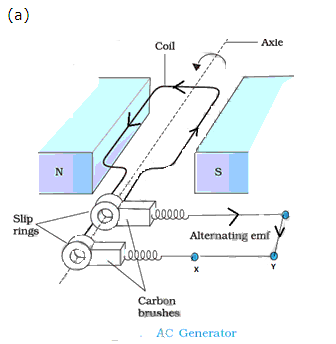
 Image From these observations, we conclude that a potential difference is induced in the coil -2 whenever the electric current through the coil - 1 is changing (starting or stopping). This process, by which a changing magnetic field in a conductor induces a current in another conductor, is called electromagnetic induction. To determine the direction of induced current, we use Fleming's left hand rule: Stretch the thumb, forefinger and middle finger of right hand so that they are perpendicular to each other. If the forefinger indicates the direction of the magnetic field and the thumb shows the direction of motion of conductor, then the middle finger will show the direction of induced current. Magnitude of induced current can be measured wi th the help of a galvanometer.

View full question & answer
Question 55 Marks
Name the material and type of wires for the following:
(a) Connecting wires for lighting
(b) Fuse wire
(c) Heating elements
(d) Connecting wires of a power line
(e) Earthing elements
Answer
(a) Connecting wires: Materials having low resistance low resistivity and high melting point e.g. copper, aluminium.
(b) Fuse wire: Materials having high resistance and low melting point e.g. solder an alloy of lead and tin.
(c) Heating element: Materials having high resistivity and high melting point e.g. tungsten.
(d) Connecting wire of a power line: Materials having low resistance and non-corosive properties e.g. high tension wires.
(e) Earthing elements: Materials which are good conductors of electricity. Earthing elements are copper wire, copper plate, salt.
View full question & answer
Question 65 Marks
Describe the construction and working of a filament lamp. List the material used and state why they are suitable for their purpose in this lamp.
Answer
Construction and working of filament bulb
List of materials used:
Light bulbs have two metal contacts, which connect to the ends of an electrical circuit. The metal contacts are attached to two stiff wires, which are attached to a thin metal filament. The filament sits in the middle of the bulb, held up by a glass mount. The wires and the filament are housed in a glass bulb, which is filled with an inert gas, such as argon.

Image 
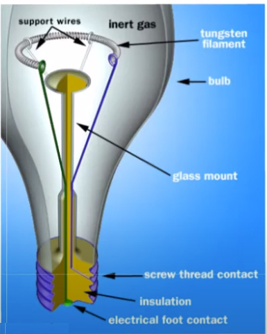
When the bulb is connected to a power supply, an electric current flows from one contact to the other, through the wires and the filament.
As the electrons zip along through the filament, they are constantly bumping into the atoms that make up the filament. The energy of each impact vibrates an atom -- in other words, the current heats the atoms up.
Metal atoms release mostly infrared light photons, which are invisible to the human eye. But if they are heated to a high enough level -- around 4,000 degrees Fahrenheit in the case of a light bulb -- they will emit a good deal of visible light.
Tungsten is used in nearly all incandescent light bulbs because it is an ideal filament material.
In a modern light bulb, inert gases, typically argon, greatly reduce this loss of tungsten. At extreme temperatures, the occasional tungsten atom vibrates enough to detach from the atoms around it and flies into the air resulting in its evaporation. In the rpesence of argon gas around it, the chances are that it will collide with an argon atom and bounce right back toward the filament, where it will rejoin the solid structure. Also since inert gases normally don't react with other elements, there is no chance of the elements combining in a combustion reaction.

View full question & answer
Question 75 Marks
Electrical appliances have voltage and power ratings as listed below. Which
has the larger working resistance?
Appliances Voltage (V) Power (W)
(a) Washing machine 250 3000
( b) Television 240 160
(c)240 240 1500
( d) Hair curler 250 20
( e) Car head lamp 12 36
Answer
Appliances Voltage (V) Power (W) Resistance (R in 0
=V2/P)
(a) Washing machine 250 3000 20.8
( b) Television 240 160 360
(c)240 240 1500 38.4
( d) Hair curler 250 20 3125
( e) Car head lamp 12 36 4

Therefore, hair curier has the largest working resistance

View full question & answer
Question 85 Marks
Explain, why is the p.d. between the terminals of a storage battery less when it is supplying current than when it is on open circuit. A battery of e.m.f. 10 volts and internal resistance 2.5 ohms has two resistances of 50 ohms each connected to it. Calculate the power dissipated in each resistance
(a) When they are in series,
(b) When they are in parallel.
In each case calculate the power dissipated in the battery.
Answer
In an open circuit no current is drawn from the cell whereas in closed circuit, an amount of energy is spent in the flow of unit positive charge through the electrolyte of the cell. Thus, the p.d. between the terminals of a storage battery is less when it is supplying current.
Given, emf e =$10 \mathrm{~V}$, internal resistance $r=2.5 \Omega$
Two external resistances $R_1=R^2=50 \Omega(=R$, say $)$
(a) When$\mathrm{R}_1$ and $\mathrm{R}_2$ are connected in series, same current flows through each resisto and hence same power is dissipated in each resistor.
Total resistance of the circuit, $R_s=R_1+R_2+r=50+50+2.5=102.5 \Omega$
Current through each resistor = $\frac{\mathrm{e}}{\mathrm{R}_{\mathrm{s}}}=\frac{10}{102.5}=0.096 \mathrm{~A}$
Power dissipated in each resistor =$I^2 R(0.096)^2(50)=0.46$ watt
(b) When $\mathrm{R}_1$ and $\mathrm{R}_1$ are connected in parallel, voltage across each resistor is same and hence same power is dissipated in each resistor.
Total resistance of the circuit $\mathrm{R}_{\mathrm{p}}=\left(\frac{1}{\mathrm{R}_1}+\frac{1}{\mathrm{R}_2}\right)^{-1}+r=25+2.5=27.5 \Omega$
Current through the circuit,$I=\frac{e}{R_p}=\frac{10}{27.5}=0.36 \mathrm{~A}$
Voltage across each resistor, V = e -Ir= 10 - ( 0.36 x 2.5) = 9.1V
Power dissipated in each resistor $P=\frac{V^2}{R}=\frac{(9.1)^2}{50}=4140.5$ watt
View full question & answer
Question 95 Marks
An electric kettle has a heating element which is rated at 2 kW when connected to a 250 V electric supply. Calculate the
(a) Current which flows in the element when it is connected to a 250 V supply,
(b) Resistance of the filament,
(c) Heat produced in 1 minute by the element,
(d) Cost of running the kettle for 10 minutes a day for 30 days of the month, at the rate of Rs. 3.00 per unit.
Answer
Given power P = 2k W = 2000 W, Voltage = 250 V
(a) Current $I=\frac{P}{V}=\frac{2000}{250}=8 \mathrm{~A}$
(b) Resistance R = $\frac{\mathrm{V}^2}{\mathrm{R}} \mathrm{t}=\frac{(250)^2}{31.25} \times 60=1.2 \times 10^5$ Joules
(d)Energyconsumedperday=$=P \times t=2 \times\left(\frac{10}{60}\right)=0.33 \mathrm{kWh}$
Energy consumed in 30 days= 0.33 x 30 = 10 kWh
Cost of running it @Rs3 per unit = 10 x 3 =Rs 30
View full question & answer
Question 105 Marks
The following appliances are to be used on 240 V supply. Calculate the current used by each and say which fuse, 2 amp, 5 amp or 13 amp should be incorporated with each, (i) A television rated at 150 W, (ii) An electric iron rated at 750 W, (iii) An immersion heater rated at 3000 W, (iv) A hair dryer rated at 500 W. How much will it cost to run the television set for 100 days for an average of 4 hours a day at 60 paise per unit?
Answer
We know that $\mathrm{P}=\mathrm{VI}$
$\mathrm{I}=\frac{\mathrm{P}}{\mathrm{V}}$
Given voltage supply= 240 Volt
(i) Current through television = $=\frac{150}{240}=0.625 \mathrm{~A}$Thus, a fuse of rating 2 A should be used with it.
(ii) Current through electric iron =$\frac{750}{240}=3.125 \mathrm{~A}$Thus, a fuse of rating 5 A should be used with it.
(iii) Current through immersion heater $=\frac{3000}{240}=12.5 \mathrm{~A}$
Thus, a fuse of rating 13 A should be used with it.
(iv) Current through hair dryer = $\frac{500}{240}$ = 2.08 A
Thus, a fuse of rating 5 A should be used with it.
(v) Energy consumed by t.v. set in 100 days when used for 4 hrs per day
$=\frac{150}{1000} \times 4 \times 100$ = 60 kWh
Cost of running it for 100 days @Rs. 0.6 per unit= 60 x 0.6 =Rs 36
View full question & answer
Question 115 Marks
The circuit diagram (Fig.) shows a battery of e.m.f. 6 volts and internal
resistance of 0.8 Ω oonnected in series. Find the
(a) Current reoorded by the ammeter,
(b) P.d. across the terminals of the resistor B,
( c) Current passing through each of the resistors B, C and D, and
( d) P.d. across the terminals of the battery.

Image

Answer
Given, emf e = 6 V, internal resistance $\mathrm{r}=0.8 \Omega$
In the given circuit, parallel combination of resistances $2 \Omega$ and $3 \Omega$
is connected in series with a $3 \Omega$ resistance.
Resistance in parallel, $\frac{1}{R_p}=\frac{1}{2}+\frac{1}{3}=\frac{5}{6} \Omega$
$R_p=1.2 \Omega$
Total resistance of the given circuit,$R_t=0.8+3+1.2=5 \Omega$
current recorded by the ammeter, $\mathrm{I}=\frac{\mathrm{e}}{\mathrm{R}_{\mathrm{t}}}=\frac{6}{5}=1.2 \mathrm{~A}$
(b) P.d. across resistor B = 1.2 x 3 = 3.6 V
(c) Current passing through resistor B = 1. 2 A
Current through resistor $C=\frac{1 \times 3}{2+3}=\frac{1.2 \times 3}{5}=0.72 \mathrm{~A}$
Current through resistor $D=\frac{1 \times 2}{2}+3=\frac{1.2 \times 2}{5}=0.48 \mathrm{~A}$
(d) p.d. across the terminals of battery= 1.2 x 0.8 = 0.96 V
View full question & answer
Question 125 Marks
Fig. represents the circuit used for the verification of ohm's law. Label the different parts from A and F. State the function of each.

Image

Answer
Image

Functions:
(A) Cell- It provides the potential difference in the circuit.

(B) Key- It serves as a switch in the circuit. It supplies or cuts off current as required.

(C) Ammeter - It measures the current in the circuit.

(D) Rheostat- It helps to change the resistance of the circuit without changing its voltage.

(E) Resistor- It provides a constant resistance in the circuit.

(F) Voltmeter - It measure the potential drop across the resistor.

View full question & answer
Question 135 Marks
An electric bulb is rated 250 W, 230 V. What information does this convey? Calculate the current through a 60 W lamp rated for 250 V. If the line voltage falls to 200 V, how is the power consumed by the bulb affected?
Answer
An electric bulb is rated 250 W-230V'; means that if the bulb is lighted on a 230V supply it consumes 25 ow electrical power or 25 OJ of electrical energy converts into heat and light in 1 second.
The safe Ii m it of current through the bulb is:
$I=\frac{P}{V}=\frac{250}{230}=1.1 \mathrm{~A}$
Current through a 60W lamp rated for 250V is:
$I=\frac{P}{V}=\frac{60}{250}=0.24 \mathrm{~A}$
We know that resistance of an appliance remains constant
.Resistance of the 1 amp =
$R=\frac{P}{I^2}=\frac{60}{(0.24)^2} \Omega$
If the line voltage falls to 200 V, power =
$P=\frac{V^2}{R}=\frac{200 \times 200 \times(0.24)^2}{60}=38.4$ watt
Thus power of the lamp reduces to 38. 4 watt.
View full question & answer
Question 145 Marks
Name any four components of an electric circuit. Write their symbols also.
Answer
Four components of an electrical circuit
(i) Cell Image
(ii) A load (bulb) Image
(iii) KeyImage
(iv) Connecting wire Image
View full question & answer
Question 155 Marks
A current of 0.3 A is flowing through a branch of 6 Ω resistors in a junction as shown in fig. . Calculate the
(a) P.d. across the junction XY,
(b) Current flowing through 9Ω and 24Ω
( c) P.d. across 24 Ω resistor, and
( d) e.m.f. of the cell.

Image

Answer
(a) Potential difference across XY = pot. cliff. across $6 \Omega$resistor
= 0.3 x 6=1.8V
(b) Pot. difference across $9 \Omega$ resistor= pot. cliff. across $6 \Omega$ resistor= 1.8 V
:. Current through $9 \Omega$ resistor =$\frac{1.8}{9}=0.2 \mathrm{~A}$
Current through $2.4 \Omega$ resistor = total current in the circuit = 0.3 + 0.2 = 0.5A
(c) p.d. across$2.4 \Omega$ resistor = 0.5 x 2.4 = 1.2 V
(d) emf of cell = p.d across $2.4 \Omega$ resistor+ pot cliff. across XY = 1.2 + 1.8 = 3.0 V
View full question & answer
Question 165 Marks
Find the effective resistance in the following circuit diagrams (Fig.):

Image

Answer
Image
The situation consists of three 10 ohm resistors connected in series between CEFD and their combination in parallel with the fourth 10 ohm resistor between C and D."
Therefore, series combination gives,$10+10+10=30 \Omega$.
This $30 \Omega$ resistor is connected in paral le I to the fourth 10 O resistor, therefore equivalent resistance between C and D,
Therefore, series combination gives, $10+10+10=30 \Omega$
This $30 \Omega$ resistor is connected in paral le I to the fourth $10 \Omega$ resistor, therefore equivalent resistance between C and D,
$\frac{1}{R}=\frac{1}{10}+\frac{1}{30}=\frac{4}{30} \Omega$
$\mathrm{R}=7.5 \Omega$
Now, between A and B the resistance Rand two $10 \Omega$ resistors are connected in series.
Therefore, equivalent resistance between A and B is
$\mathrm{R}_{\text {total }}=10+10+7.5=27.5 \Omega$
View full question & answer
Question 175 Marks
 A battery o f e.m.f. 3 Vis connected in series with an ammeter, a $10 \Omega$ coil of wire and with a parallel combination of resistance of $3 \Omega$ and $6 \Omega$. Draw a circuit diagram for the above arrangement. What is the
(a) Resistance of the parallel combination?
(b) Reading on the ammeter?
(c) Potential difference across the $3 \Omega$ resistor?
(d) Current flowing through each resistor?
Answer
Image
(a) Resistance of parallel combination:
$\frac{1}{\mathrm{R}_{\text {parallel }}}=\frac{1}{3}+\frac{1}{6}=\frac{3}{6}=\frac{1}{2} \Omega$
$\mathrm{R}_{\text {parallel }}=2 \Omega$
(b) Total resistance of the circuit =
$\mathrm{R}_{\text {total }}=2+10=12 \Omega$
Let I be the current through the ammeter, the:
$\mathrm{I}=\frac{\mathrm{V}}{\mathrm{R}_{\text {total }}}=\frac{3}{12}=\frac{1}{4}=0.25 \mathrm{~A}$
(c) Potential drop across 100 resistor, $V _1=1 \times 10=0.25 \times 10=2.5 V$
$\therefore$ Potential drop across $3 \Omega$ resistor, $V _2= e - V _1=3-2.5=0.5 V$
(d) Current flowing through $10 \Omega$ resistor $=0.25 A$
Current flowing through $3 \Omega$ resistor $=\frac{ V _2}{ R }=\frac{0.5}{3}=0.17 A$
Current flowing through $6 \Omega$ resistor $=0.25 \cdot 0.17=0.08 A$
View full question & answer
Question 185 Marks
What is the combined resistance of each of the networks between A and B shown in fig. ?

Image

Answer
(a) Between A andB,resistances$5 \Omega$ and $3 \Omega$ are connected in series
$\therefore R_S=5+3=8 \Omega$
This series combination of resistances $5 \Omega$ and $3 \Omega$ is connected in parallel with the resistance 80
:. total resistance between A and Bis given as:
$R=\left[\frac{1}{8}+\frac{1}{8}\right]^{-1}=4 \Omega$
(b) Bet ween A and B ,paralle combination of resistances 9Ω and 18Ω is connected in series with resistance 2Ω.
Parallel resistance of $9\Omega$ and $18\Omega$ is :
$R_p=\left[\frac{1}{9}+\frac{1}{18}\right]^{-1}=6 \Omega$
:. total resistance between A and B is:
$R=6+2=8 \Omega$
(c) The situation consists of three two ohm resistors connected in series between CEFD and their combination in parallel with the fourth 2 ohm resistor between C and D.
Image
Therefore, series combination gives,$2+2+2=6 \Omega$.
This 6Ω resistor is connected in para lie I to the fourth 2Ω n resistor, therefore equivalent resistance between C and D,
$\frac{1}{R}=\frac{1}{6}+\frac{1}{2}=\frac{2}{3} \Omega$
$\therefore \mathrm{R}=1.5 \Omega$
Now, between A and B the resistance Rand two 2Ω resistors are connected in series.
Therefore, equivalent resistance between A and B is
$R_{\text {total }}=2+2+1.5=5.5 \Omega$
View full question & answer
Question 195 Marks
Fig. represents the circuit used for the verification of Ohm's law. Label the parts from A to F. state the function of each.

Image

Answer
Image

Functions:
(A) Cell- It provides the potential difference in the circuit.
(B) Key- It serves as a switch in the circuit. It supplies or cuts off current as required.
(C) Ammeter- It measures the current in the circuit.
(D) Rheostat- It helps to change the resistance of the circuit without changing its voltage.
(E) Resistor- It provides a constant resistance in the circuit.
(F) Voltmeter- It measure the potential drop across the resistor.

View full question & answer
[5 Mark Question Answer] - Physics STD 10 Questions - Vidyadip